

Micro-diffractive surveillance illuminator
a technology of diffractive surveillance and illuminator, which is applied in the direction of traffic control system, television system, heating/cooling arrangement, etc., to achieve the effect of increasing illumination distance, increasing the maximum angle of diffraction, and reducing the cost of operation
- Summary
- Abstract
- Description
- Claims
- Application Information
AI Technical Summary
Benefits of technology
Problems solved by technology
Method used
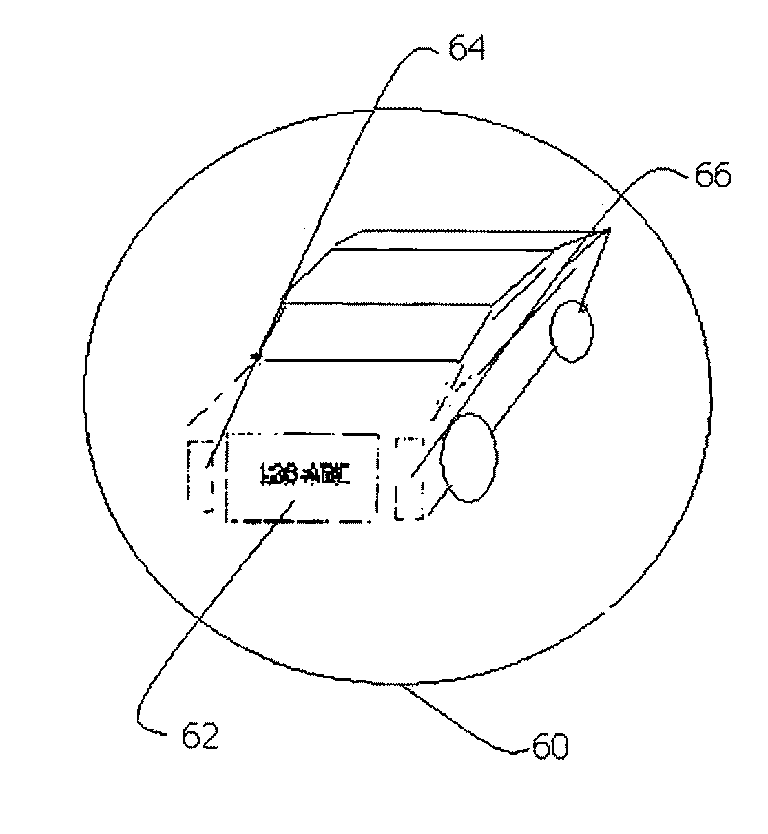
Image

Examples
Embodiment Construction
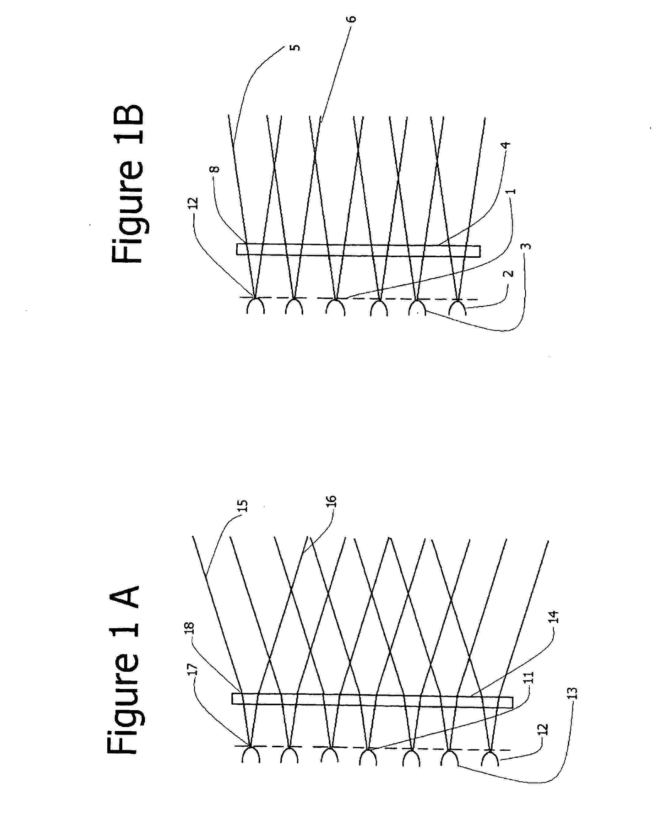
[0033]Referring to FIG. 1A, the light emitting manifold 11 seen in a top down view, which contains a number of near point-source lights such as 12 and 13, sends rays of light such as 17 through a mono-directional micro-diffractive material 14 which causes the rays of light to diverge horizontally as at point 18, so that the outgoing light rays 15 and 16 travel out from the illuminator at greater angles.
[0034]Referring to FIG. 1B, the light emitting manifold 1 is seen in a side view, with point-source light 12 shown at the top, and point-source lights 2&3 which are below the visible plane of FIG. 1A. Light from the manifold 1 passes through the micro-diffractive material 4, but the mono-directional nature of the micro-diffractive material enables the light to pass through without significant vertical divergence as a point 8. The outgoing rays of light such as 5 and 6 continue close to their initial trajectories.
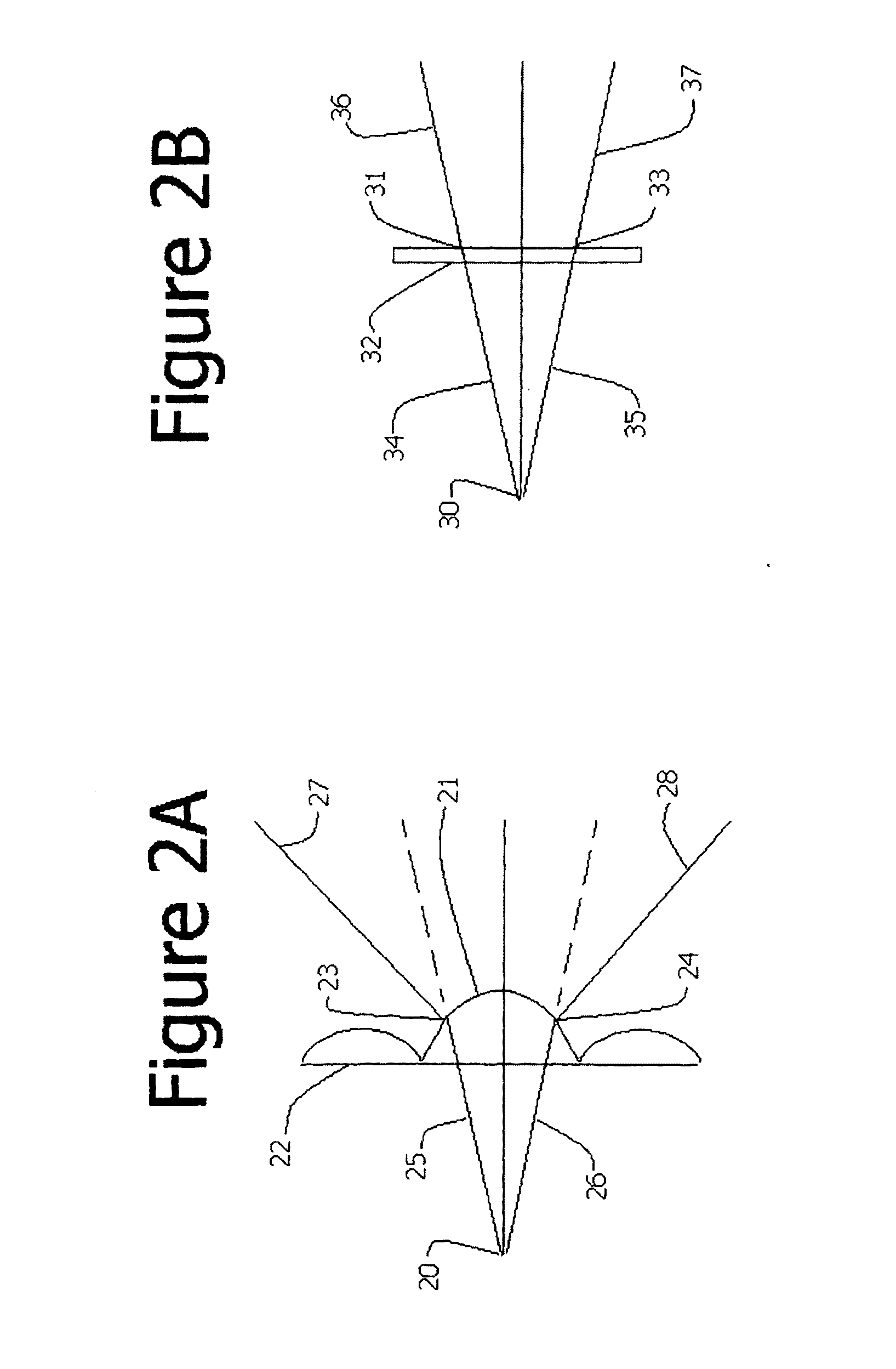
[0035]Referring to FIG. 2A, a beam of light from an LED 20 characterized ...
PUM
 Abstract
Description
Claims
Application Information