

Roller with cage assembly
a cage and roller technology, applied in the direction of needle bearings, shafts and bearings, rotary machine parts, etc., can solve the problems of shortened bearing life, skewed rollers, worn guiding surfaces,
- Summary
- Abstract
- Description
- Claims
- Application Information
AI Technical Summary
Benefits of technology
Problems solved by technology
Method used
Image

Examples
Embodiment Construction
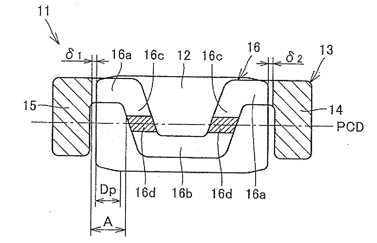
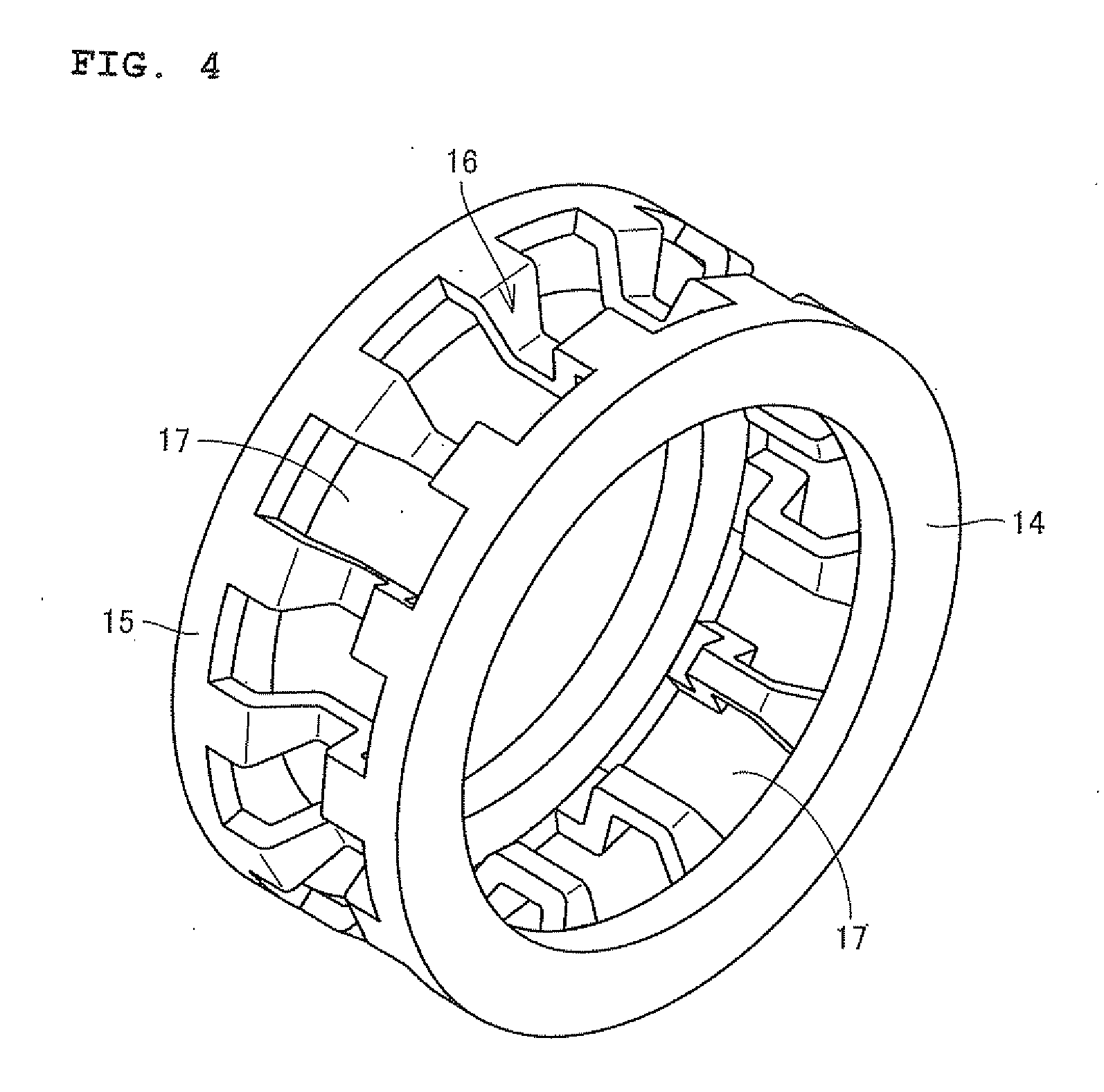
[0016]A roller with cage assembly 11 according to one embodiment of the present invention will be described with reference to FIGS. 1 to 4. FIG. 1 is a view showing the roller with cage assembly 11, FIG. 2 is a view showing a roller 12, FIG. 3 is a sectional view showing a cage 13, and FIG. 4 is a perspective view showing the cage 13. First, referring to FIG. 1, the roller with cage assembly 11 is a cage and roller type of needle roller bearing comprising the plurality of rollers 12, and the cage 13 for retaining intervals of the adjacent rollers 12.
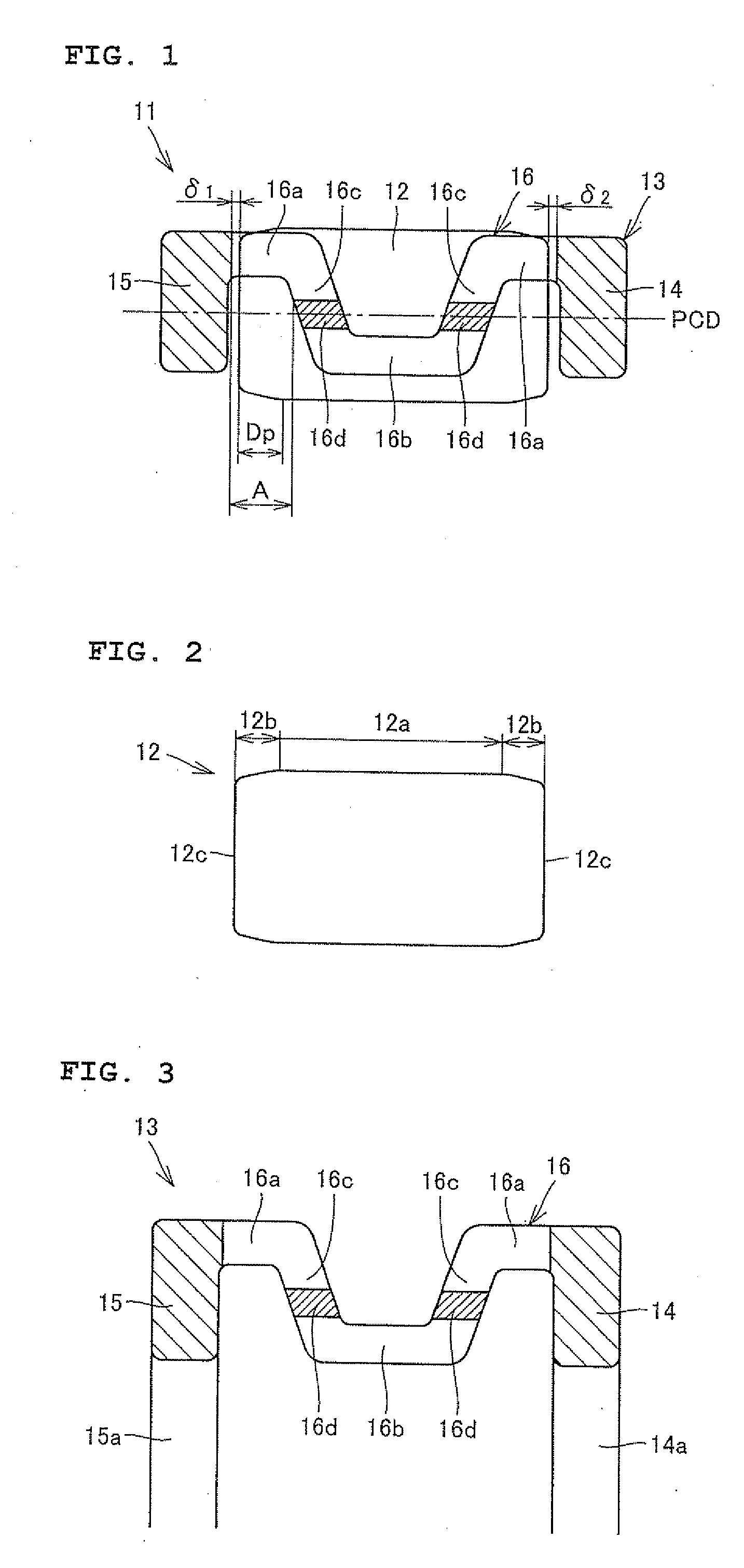
[0017]Referring to FIG. 2, the roller 12 is partially crowned and includes a column part 12a having a constant diameter and inclined parts 12b at both ends of the column part 12a. The inclined part 12b is formed such that the diameter is gradually reduced from the column part 12a toward an end face 12c.
[0018]Referring to FIGS. 3 and 4, the cage 13 includes a pair of ring parts 14 and 15, a plurality of pillar parts 16 connecting the pai...
PUM
 Abstract
Description
Claims
Application Information