Turbocharger vane

a technology of turbocharger and cylinder head, which is applied in the field of turbochargers, can solve the problems of reducing the efficiency of the engine, the cost of parts manufacture and labor involved in the assembly of such systems, and the drawback of leakage between the cylinder head and the adjacent components, so as to reduce the leakage and the effect of efficient and cost-effective structur

Active Publication Date: 2010-04-22
BORGWARNER INC
View PDF6 Cites 38 Cited by
  • Summary
  • Abstract
  • Description
  • Claims
  • Application Information

AI Technical Summary

Benefits of technology

[0018]The present disclosure provides an efficient and cost-effective structure for reducing leak

Problems solved by technology

First, the market demands that all components of the power plant of either a passenger car or truck, including the turbocharger, must provide reliable operation for a much longer period than was demanded in the past.
Other considerations include the cost of manufacture of parts and the labor involved in assembly of such systems.
While movement of the vanes allows for control of the gas delivery, it also ad

Method used


Image

  • Turbocharger vane
  • Turbocharger vane
  • Turbocharger vane

Examples


Embodiment Construction

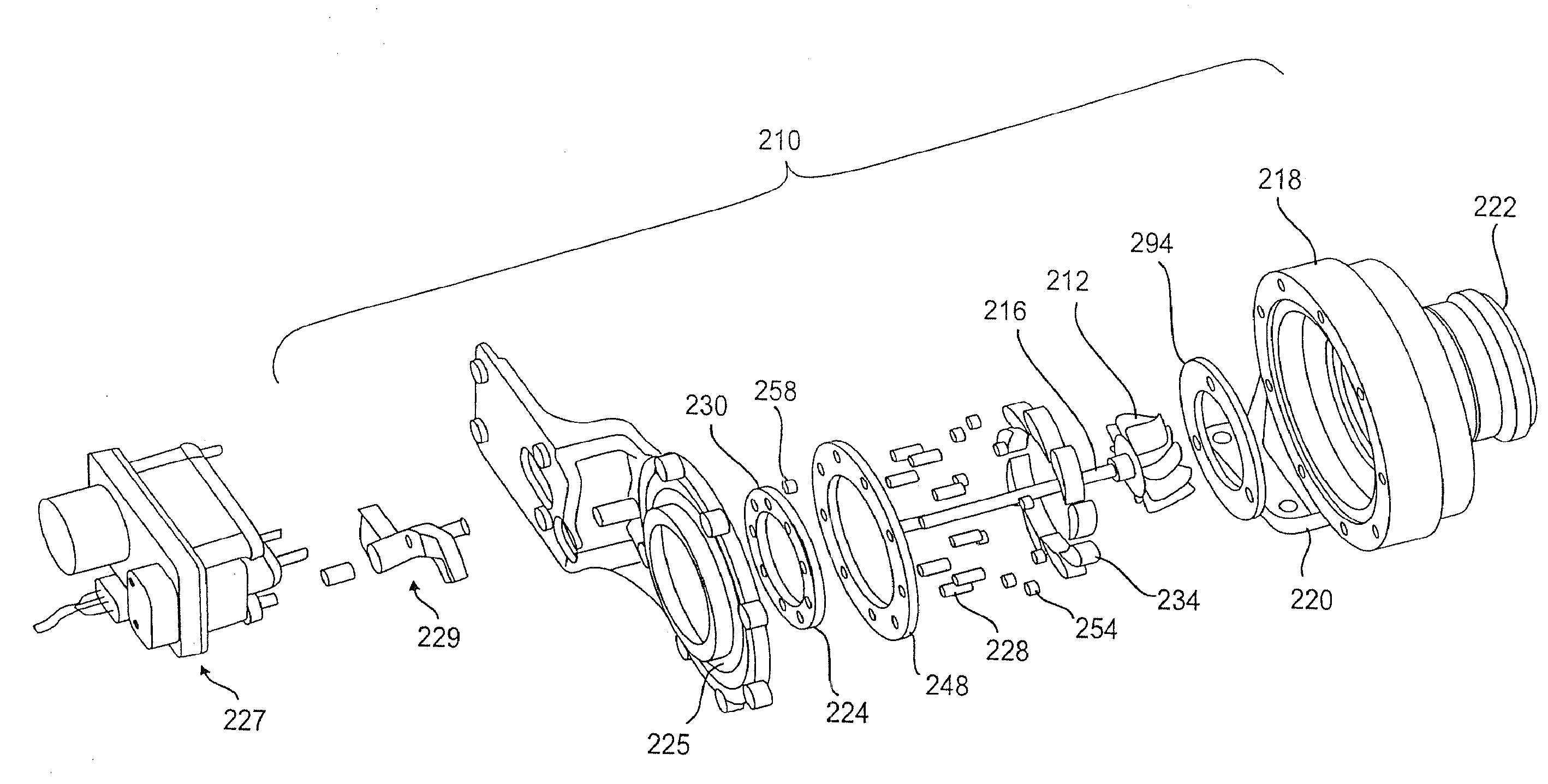
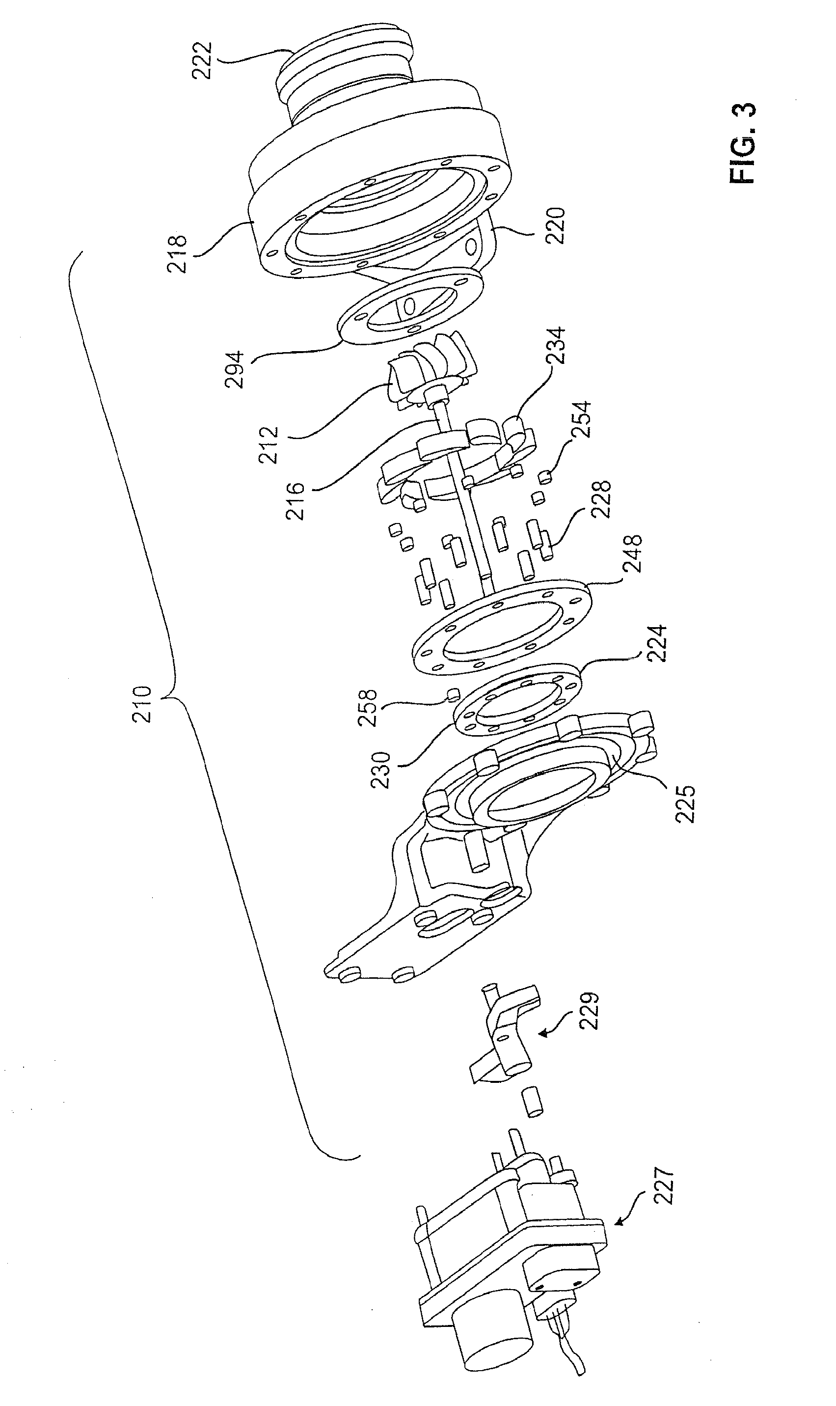
[0043]Exemplary embodiments described herein are directed to a vane assembly for a turbocharger. Aspects will be explained in connection with several possible embodiments of the vane, but the detailed description is intended only as exemplary. The particular type of turbocharger that utilizes the exemplary embodiments of the vane and vane assemblies described herein can vary. The several embodiments are described with respect to vanes for the turbine wheel, but the present disclosure contemplates use of such vanes with the compressor wheel and / or both. Exemplary embodiments are shown in FIGS. 3-12, but the present disclosure is not limited to the illustrated structure or application.

[0044]A turbocharger system as shown in FIG. 3 includes turbomachinery in the form of a turbocharger 210 generally comprising a turbine wheel 212 and a compressor impeller (not shown) mounted on opposite ends of a common shaft 216. The turbine wheel 212 may be disposed within a turbine housing 218 that i...


PUM


Abstract

A vane (234) is provided which reduces leakage of gas in a variable geometry turbocharger (210) from the high pressure side of the vane (234) to the low pressure side of the vane (234). The vane (234) can have a channel (330, 430) along a gas bearing surface (325, 425) for reducing the leakage. The channel (330, 430) can be defined at least in part by sideplates (300, 350). The sideplates (300, 350) can be integrally cast with the rest of the vane (234). At least one of the sideplates (300, 350) can have a hole therein for a vane shaft (228) which allows movement of the vane (234) for gas flow control. The 340 sideplates (300, 350) can have edges (301, 351) that conform to the shape of the gas bearing surface (325, 425).

Description

FIELD OF THE INVENTION[0001]The invention relates in general to turbochargers and, more particularly, to vanes for use in variable geometry nozzles.BACKGROUND OF THE INVENTION[0002]Turbochargers are widely used on internal combustion engines and, in the past, have been particularly used with large diesel engines, especially for highway trucks and marine applications.[0003]More recently, in addition to use in connection with large diesel engines, turbochargers have become popular for use in connection with smaller, passenger car power plants. The use of a turbocharger in passenger car applications permits selection of a power plant that develops the same amount of horsepower from a smaller, lower mass engine. Using a lower mass engine has the desired effect of decreasing the overall weight of the car, increasing sporty performance, and enhancing fuel economy. Moreover, use of a turbocharger permits more complete combustion of the fuel delivered to the engine, thereby reducing the ove...

Claims


Application Information

Patent Timeline
IPC IPC(8): F04D29/56
CPCF02B37/24F05D2220/40F05D2240/80F01D5/143F01D17/165F05D2230/21
Inventor ROBY, STEVEDECKER, DAVID M.METZ, DIETMAR
Owner BORGWARNER INC
Why Eureka
Try Eureka