Stator blade ring and axial flow compressor using the same

a technology of axial flow compressor and stator blade, which is applied in the direction of stators, machines/engines, liquid fuel engines, etc., can solve the problems of reducing compression efficiency, affecting the operation of stator blades, so as to reduce the possibility of thermal deformation and a decrease in strength, the effect of ensuring shape flexibility

Active Publication Date: 2010-04-22
MITSUBISHI POWER LTD
View PDF8 Cites 17 Cited by
  • Summary
  • Abstract
  • Description
  • Claims
  • Application Information

AI Technical Summary

Benefits of technology

[0020]With this configuration, because the connecting members do not project outward from the inner shroud portions or the outer shroud portions even if they are deformed due to thermal stress, thermal distortion can be tolerated. Furthermore, for example, when the stator blade ring segments are inserted into the guide groove in the casing, the connecting members do not touch the guide groove. Thus, the sliding area between the stator blade ring segments and the guide groove can be reduced, making assembly of the stator blade rings easy.
[0021]A second aspect of the present invention provides an axial flow compressor including the stator blade ring in which the possibilities of thermal deformation and a decrease in strength can be reduced, the shape flexibility can be ensured, and the compression performance can be improved.
[0022]According to this aspect, because the stator blade ring in which the possibilities of thermal deformation and a decrease in strength can be reduced, the shape flexibility can be ensured, and the compression performance can be improved is provided, the strength and compression performance of the axial flow compressor can be improved.
[0023]This can improve the thermal efficiency of, for example, a gas turbine.
[0024]In the present invention, the stator blade segments, each formed as a single part, are positioned at predetermined locations of the connecting members and are welded and fixed to the connecting members at a portion of the length thereof in the circumferential direction to form the arch-shaped portions (stator blade ring segments) of the stator blade ring. Thus, it is possible to reduce the risk of thermal deformation of the formed stator blade ring and to maintain sufficient structural strength.
[0025]Because turbulence of the compressed air due to thermal deformation is suppressed and the shape of the stator blades can be freely determined according to the required compression performance, predetermined compression performance can be maintained.

Problems solved by technology

Thus, the stator blades and the shrouds are subjected to great heat, which may deform the stator blades and the shrouds.
Distortion of the stator blades disturbs the air flow and decreases the compression efficiency.
Furthermore, distortion of the shrouds makes, for example, the inner surfaces of the shrouds wavy.
This creates gaps between the inner surface of a casing of the chamber and the inner surfaces of the shrouds, disturbing the flow in the chamber and decreasing the compression performance.

Method used


Image

  • Stator blade ring and axial flow compressor using the same
  • Stator blade ring and axial flow compressor using the same
  • Stator blade ring and axial flow compressor using the same

Examples


Embodiment Construction

[0049]A gas turbine according to an embodiment of the present invention will be described below with reference to FIGS. 1 to 5.

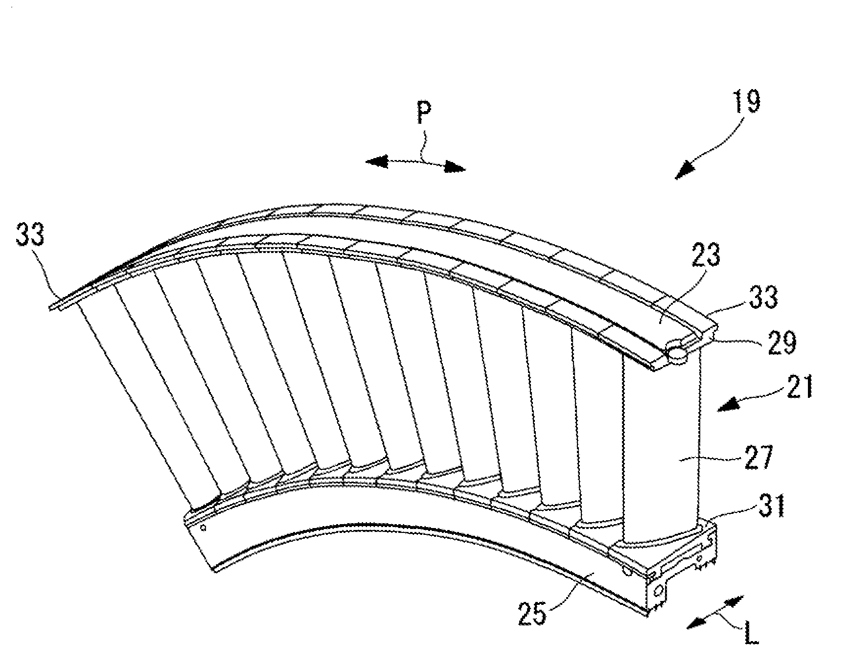
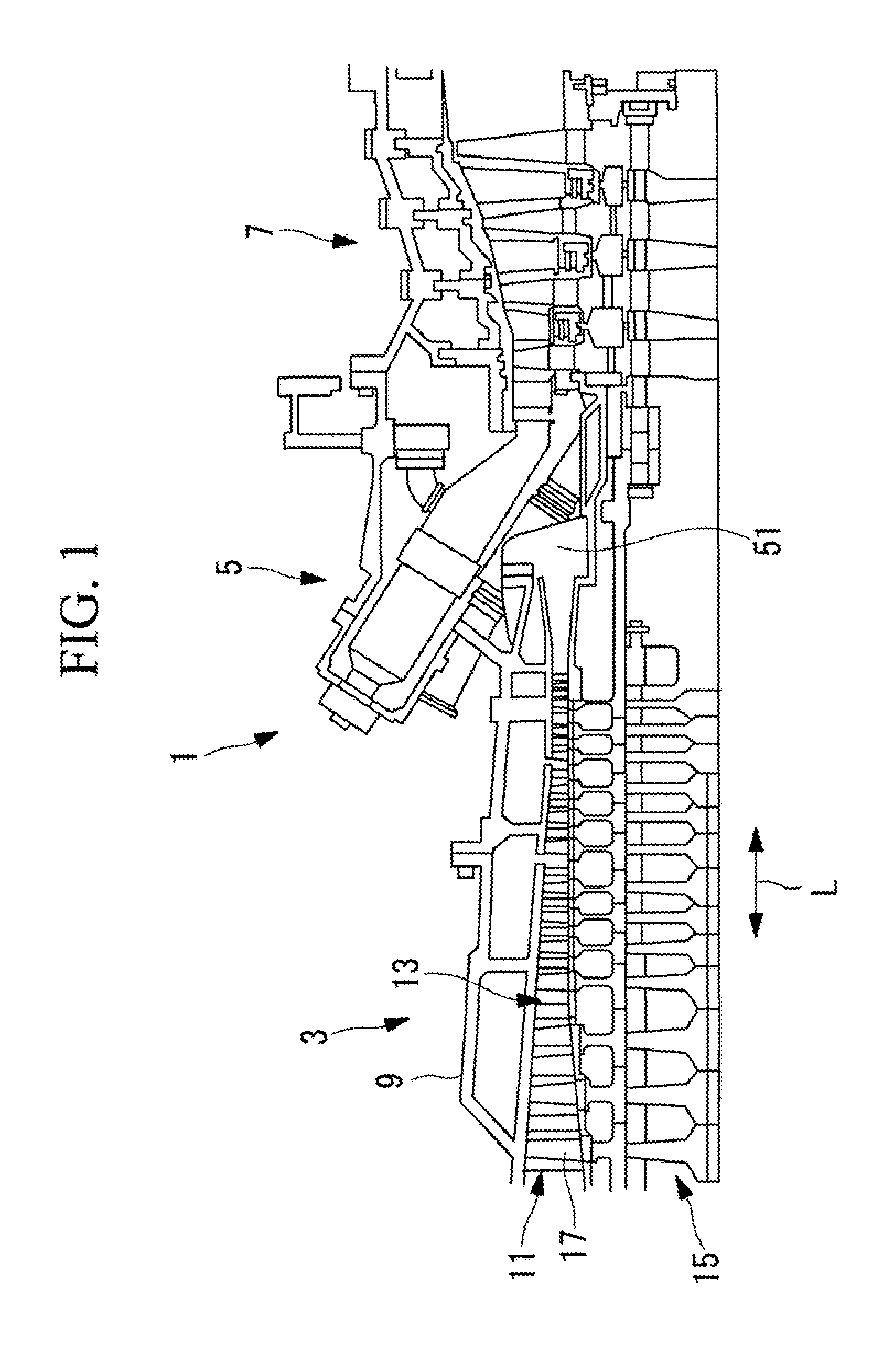
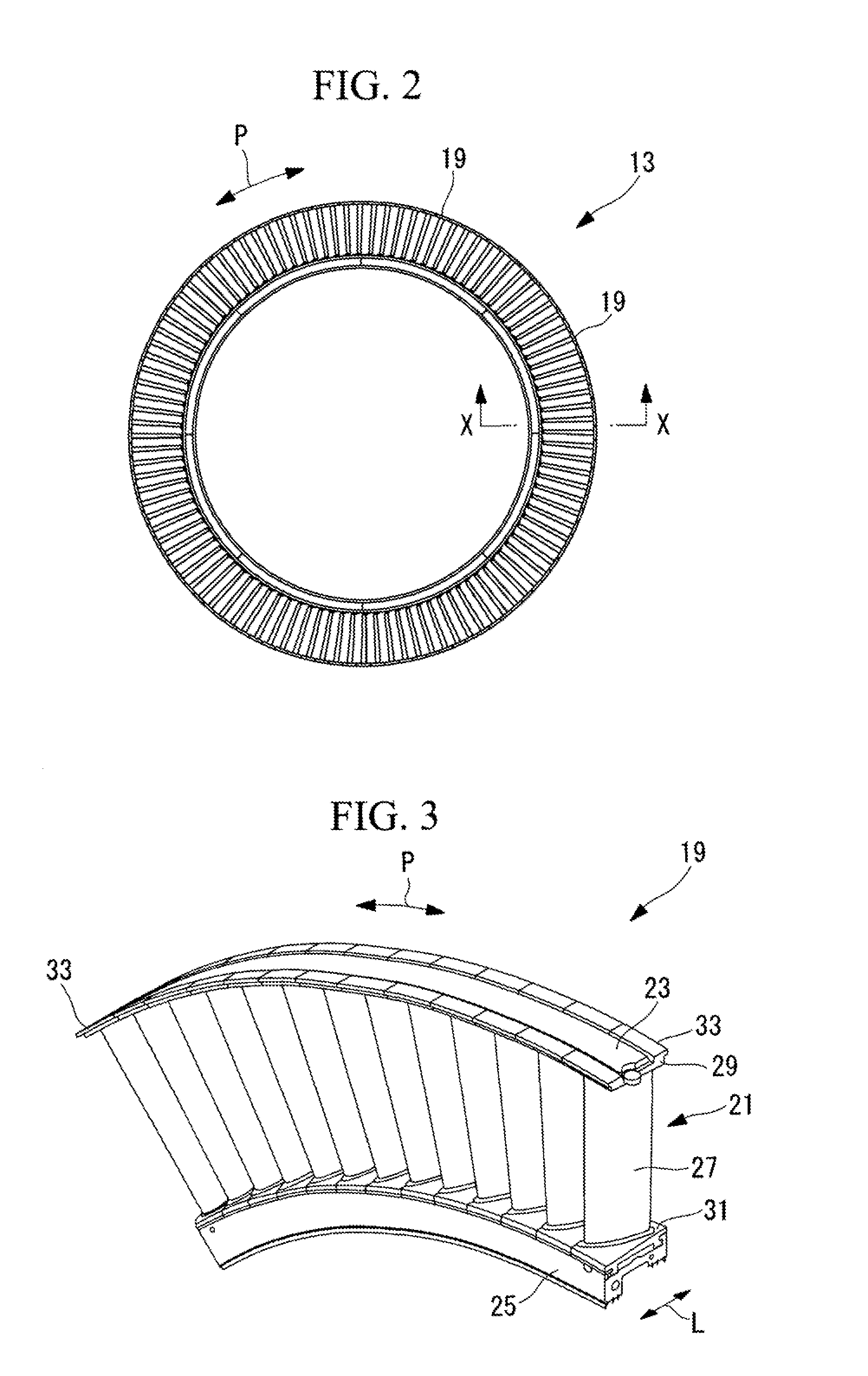
[0050]FIG. 1 is a schematic sectional view showing an upper half of a gas turbine 1 according to this embodiment. FIG. 2 is a side view showing a stator blade ring 13 according to this embodiment. FIG. 3 is a perspective view showing a stator blade ring segment 19 according to this embodiment. FIG. 4 is a sectional view taken along line X-X in FIG. 2. FIG. 5 is a partial plan view of the stator blade ring segment 19, viewed from the outside.

[0051]As shown in FIG. 1, the gas turbine 1 includes a compressor (axial flow compressor) 3 that compresses air, combustors 5 that combust fuel using the air compressed by the compressor 3, and a turbine 7 to which combustion gas from the combustors 5 is guided. The components of the gas turbine 1, including the compressor 3, the combustors 5, and the turbine 7, are covered by a casing 9.

[0052]The compressor 3 is an axial...


PUM


Abstract

A stator blade ring is provided with which the possibilities of thermal deformation and a decrease in strength can be reduced, the shape flexibility can be ensured, and the compression performance can be improved. It includes stator blade segments (21) in each of which an inner shroud portion (31) and an outer shroud portion (29) divided corresponding to one stator blade (27) are provided at both ends of the stator blade (27) so as to be formed as a single part, and connecting members (23) that are formed of arch-shaped plates and are disposed on at least one of the inner shroud portions (31) and the outer shroud portions (29) of the stator blade segments (21) adjoining in a circumferential direction, on a side opposite to the stator blades (27). The stator blade segments (21) are welded to the connecting members (23) at a portion of the length thereof in the circumferential direction.

Description

TECHNICAL FIELD[0001]The present invention relates to axial flow compressors such as gas turbine compressors, and more specifically, to stator blade rings of the axial flow compressors.BACKGROUND ART[0002]In a stator blade ring of an axial flow compressor, multiple (for example, several tens to several hundreds) stator blades are arranged at substantially equal intervals in the circumferential direction.[0003]As shown in Patent Documents 1 and 2, for example, many of the conventional stator blade rings are assembled in such a manner that both ends of the stator blades are fitted into holes in inner and outer shrouds constituting chamber walls to be temporarily mounted, and electron-beam welding is performed in the circumferential direction from the side surfaces of the shrouds to join the stator blades and the inner and outer shrouds.[0004]Patent Document 1: Japanese Examined Patent Application, Publication No. Sho 58-57276[0005]Patent Document 2: Japanese Examined Patent Applicatio...

Claims


Application Information

Patent Timeline
Patent Type & Authority Applications(United States)
IPC IPC(8): F01D9/04
CPCF01D9/041F01D25/26F05D2230/235F05D2220/3216F01D25/246F04D29/542F04D29/023F05D2230/233F01D9/04F01D9/02F01D25/00F02C7/00
Inventor HAMANA, HIROYUKI
Owner MITSUBISHI POWER LTD
Why Eureka
Try Eureka