Modular Shower Cabin For Aircrafts

a shower cabin and module technology, applied in the field of modules for aircraft shower cabins, can solve the problems of high cost, large effort, and inability to individually replace, and achieve the effect of reducing the manufacturing cost of the shower cabin and being easy to access for being repaired

Inactive Publication Date: 2010-04-29
LUFTHANSA TECH AG
View PDF52 Cites 8 Cited by
  • Summary
  • Abstract
  • Description
  • Claims
  • Application Information

AI Technical Summary

Benefits of technology

[0010]It is further proposed that the center portion is formed by at least two structural components, and that the structural components are connected with each other at their vertically running sides. Thereby, the center portion can be formed to have different cross-sectional geometries, for example as a barrel having a circular cross-section, as a cuboid having a rectangular cross-section, or with any radii in adaptation to the mounting conditions in the aircraft cabin. It is important in this respect that the joints run vertically or are hidden in the form of vertically running edges and thus do not cut the recesses.
[0011]It is further proposed that at least one of the structural components has a radius, and that the structural component at the end of the radius passes into a planar side wall. As the shower cabin often is located adjacent to side walls of an aircraft cabin which are arranged at an angle in particular at a right angle to each other, a free space between the shower cabin and the side walls adjacent to each other is provided by the radius, in which free space the faucet unit can be attached to the shower cabin from the outside, whereas with the planar side wall the shower cabin then rests against the side wall of the aircraft cabin.
[0012]In this case, it is particularly advantageous if at least two structural components having an identical radius are provided and the structural components are joined together in such a way that the planar opposite side walls are located to be parallel to each other. In this case, structural components having an identical basic shape can be used which can be produced in a joint form or a joint manufacturing process. By using a joint form for producing the structural components the manufacturing costs for the shower cabin are significantly reduced.
[0013]It is particularly easy to adapt the shaping of the shower cabin to the mounting conditions available in the aircraft cabin by the planar side walls adjacent to each other having different widths. The structural components in particular can then initially be produced to be oversized and subsequently they can be adapted to the respective mounting conditions by individually cutting the planar side walls to size. The only unchangeable geometry is the radius to which the faucet unit is connected.
[0014]It is further proposed that at least one ventilation gap is provided between the center portion and the ceiling portion. The ventilation gap can be realized by the geometric design of the outer contour of the ceiling portion or the geometric design of the inner contour of the center portion so that it automatically takes shape when the portions are joined together. The cross-section of the ventilation gap in particular can be chosen independent of other components in such a way that the humid air present in the shower cabin can be sucked off to a sufficient extent and silently.
[0015]A further preferred design of the invention is that the bottom portion and / or the ceiling portion are covered by a detachable cover plate towards the interior of the shower cabin. Thus, on the one hand, the technical facilities are hidden optically, and, on the other hand, are easy to access for being repaired by removing the cover plate.

Problems solved by technology

It is a disadvantage of this embodiment that the upper and the lower segment have to be joined together very accurately, in order that the joint is preferably not visible at all or at least runs evenly so that the harmonic overall impression is preferably not irritated by the joint and the large recess of the entrance area taking shape when the segments are joined together is as accurate to shape as possible.
Furthermore, due to integrating the technical facilities into the segments it is not possible to individually replace them in the event of repair, as they are hard to access from inside the shower cabin.
In an extreme case, the whole shower cabin needs to be dismounted for repairing one of the technical facilities involving great effort and high costs.

Method used


Image

  • Modular Shower Cabin For Aircrafts
  • Modular Shower Cabin For Aircrafts
  • Modular Shower Cabin For Aircrafts

Examples


Embodiment Construction

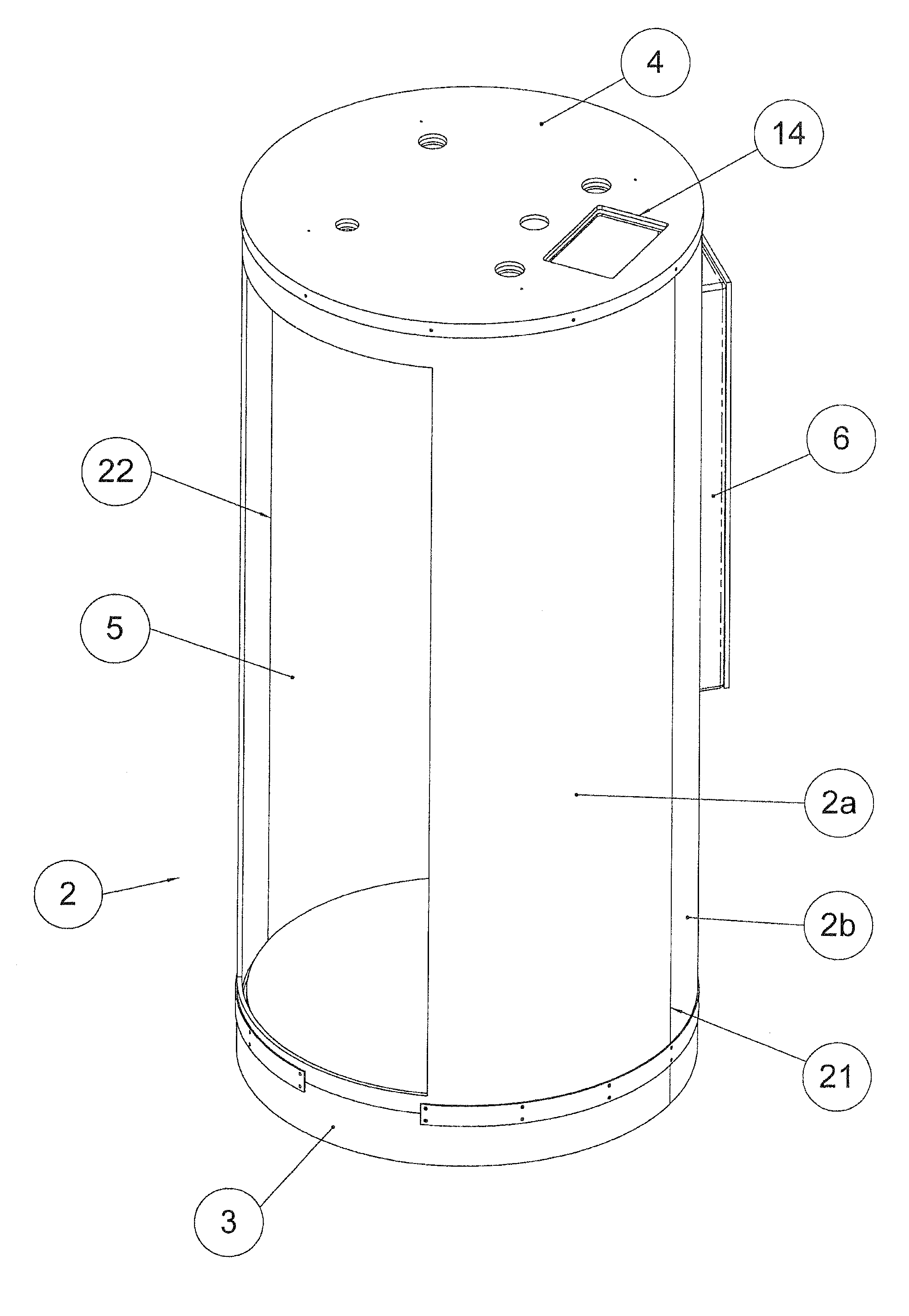
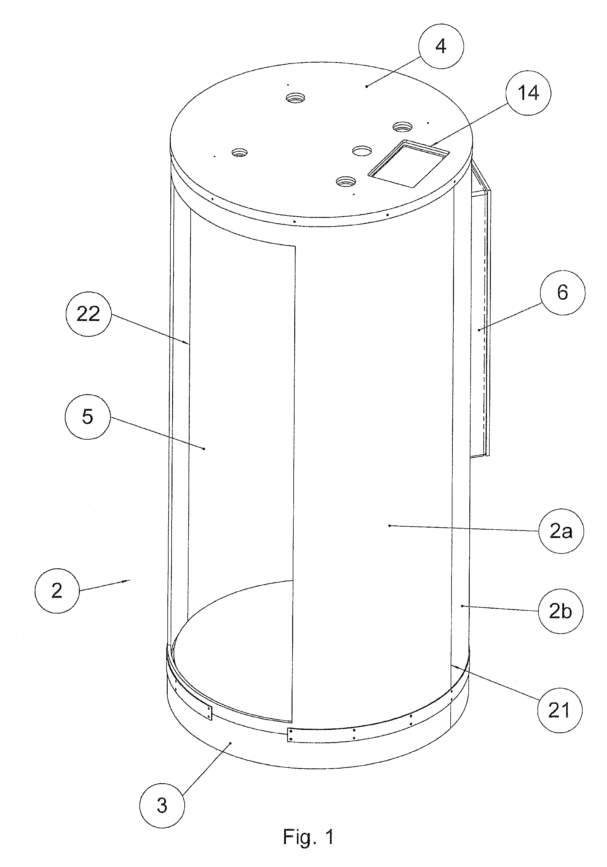
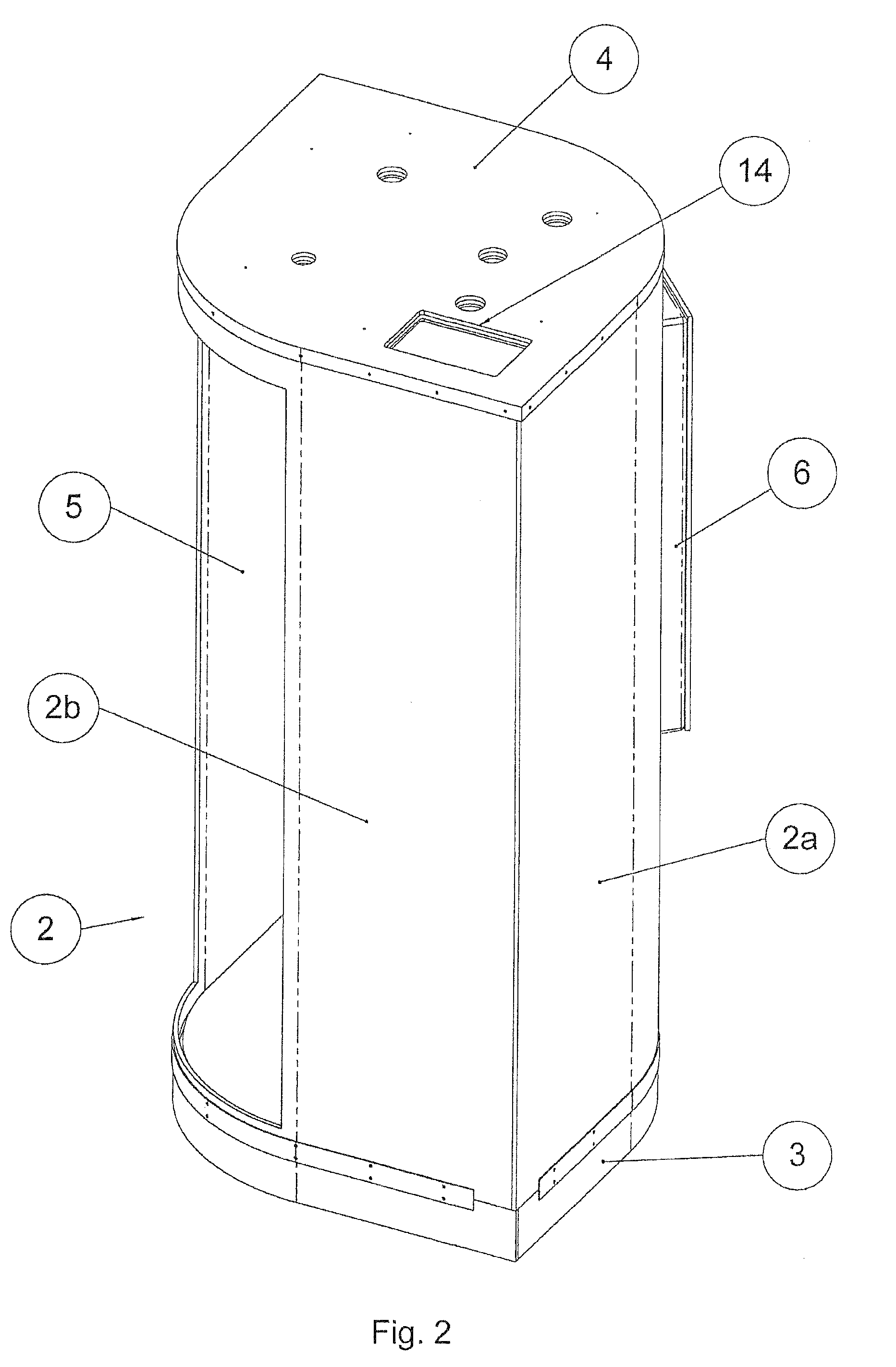
[0032]The indications of location and direction in the following description of the modular shower cabins always relate to a shower cabin in the upright position.

[0033]First of all, FIG. 1 shows a modular shower cabin comprising a barrel-shaped center portion 2. The barrel-shaped center portion 2 is limited towards the top by the ceiling portion 4 and towards the bottom by the bottom portion 3, and is formed by two structural components 2a and 2b having been joined together. The structural components 2a and 2b are designed to have the shape of a divided circle and are joined together at their vertical side edges 21 and 22 so that the cross-section of a full circle takes shape, as can also be seen in FIG. 6 in the viewing direction from the bottom to the bottom portion 3 with the drain 15 located in the center. A recess 5 is provided in the structural component 2a, which recess forms the entrance area and due to the design of the shower cabin according to the invention now is provide...


PUM


Abstract

The invention relates to a modular shower cabin for aircrafts comprising an integratable faucet unit (6), and integrated technical facilities, like for example a water drain (15), illumination, a ventilation device, oxygen masks or the like, wherein the shower cabin comprises a center portion (2), in which an entrance area formed by a recess (5) and a mounting for the faucet unit (6) are provided, and wherein the shower cabin comprises a ceiling portion (4) adjoining the center portion (2) at the top, and a bottom portion (3) adjoining the center portion (2) at the bottom, and wherein the technical facilities are allocated to the ceiling portion (4) and/or to the bottom portion (3).

Description

RELATED APPLICATION[0001]The application claims priority under 35 U.S.C. §119(e) of German Patent Application No. DE 102008053228.2, filed on Oct. 27, 2008, which is hereby incorporated by reference in its entirety.FIELD OF INVENTION[0002]The invention relates to a modular shower cabin for aircrafts.BACKGROUND OF INVENTION[0003]In aircrafts, shower cabins are provided for example as special equipment or in the first class area, where these then need to meet highest optical as well as haptic quality demands being standard in this class. These shower cabins further need to comprise certain technical facilities, like for example illumination, faucets, water drain, ventilation, oxygen masks, which preferably are pre-assembled with the shower cabin when being mounted in the aircraft, in order to reduce the time required for the initial mounting in the aircraft. As the space available in the aircraft is limited, the shower cabin itself and the arrangement of the connections as well as of ...

Claims


Application Information

Patent Timeline
Patent Type & Authority Applications(United States)
IPC IPC(8): A47K3/28
CPCB64D11/02A47K3/284A47K3/286
Inventor VON OBSTFELDER, NICO
Owner LUFTHANSA TECH AG
Why Eureka
Try Eureka