Ion gate for dual ion mobility spectrometer and method thereof

a technology of mobility spectrometer and ion gate, which is applied in the field of ion gate for dual ion mobility spectrometer and the method thereof, can solve the problems of poor instrument sensitivity, high production cost, and high assembly requirements, and achieve the effect of improving the utility rate of ions

Active Publication Date: 2010-04-29
NUCTECH CO LTD +1
View PDF6 Cites 10 Cited by
  • Summary
  • Abstract
  • Description
  • Claims
  • Application Information

AI Technical Summary

Benefits of technology

[0019]With the ion gate and the method of the present invention, after sample gas enters the ion gates, charge exchange with reaction ions occurs between the first gate electrode and the second electrode, and positive and negative ions (sample ions, reaction ions) are continuously stored into the storage regions for the positive and negative ions. This leads to an improvement of utility rate of ions. Then, the ions are educed in a step-wise manner from the storage regions for the positive and negative ions by a simple control of a combination of the electrodes.

Problems solved by technology

Patent Document 1 offers an advantage of a simple control of ions, while it has a disadvantage of complex manufacture process for the ion gate, strict requirements on assembly and high produce cost.
Further, the effective utility rate of ions is low.
The structure of the gates causes a loss of about 90% of the total ions inside the gates, leading to poor instrument sensitivity.
Unfortunately, both of the positive and negative ions are stored in the same area in the ion trap, and thus part of the ions is lost due to the charge exchange between the ions.
Further, the quad-polar ion trap has a complex structure and thus a very stringent requirement for concentricity and assembly, leading to a higher fabrication cost.
Also, the scheme of electrode control is relatively complicated, which makes control over the whole apparatus more difficult.

Method used


Image

  • Ion gate for dual ion mobility spectrometer and method thereof
  • Ion gate for dual ion mobility spectrometer and method thereof
  • Ion gate for dual ion mobility spectrometer and method thereof

Examples


first embodiment

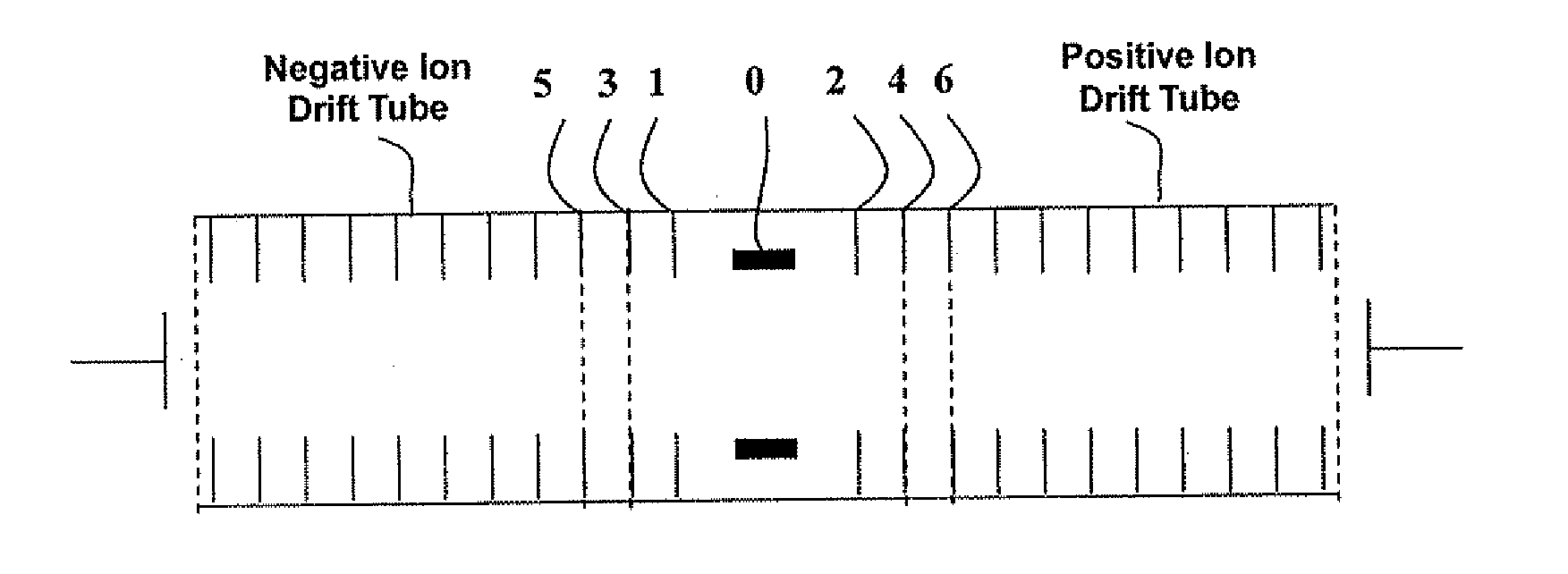
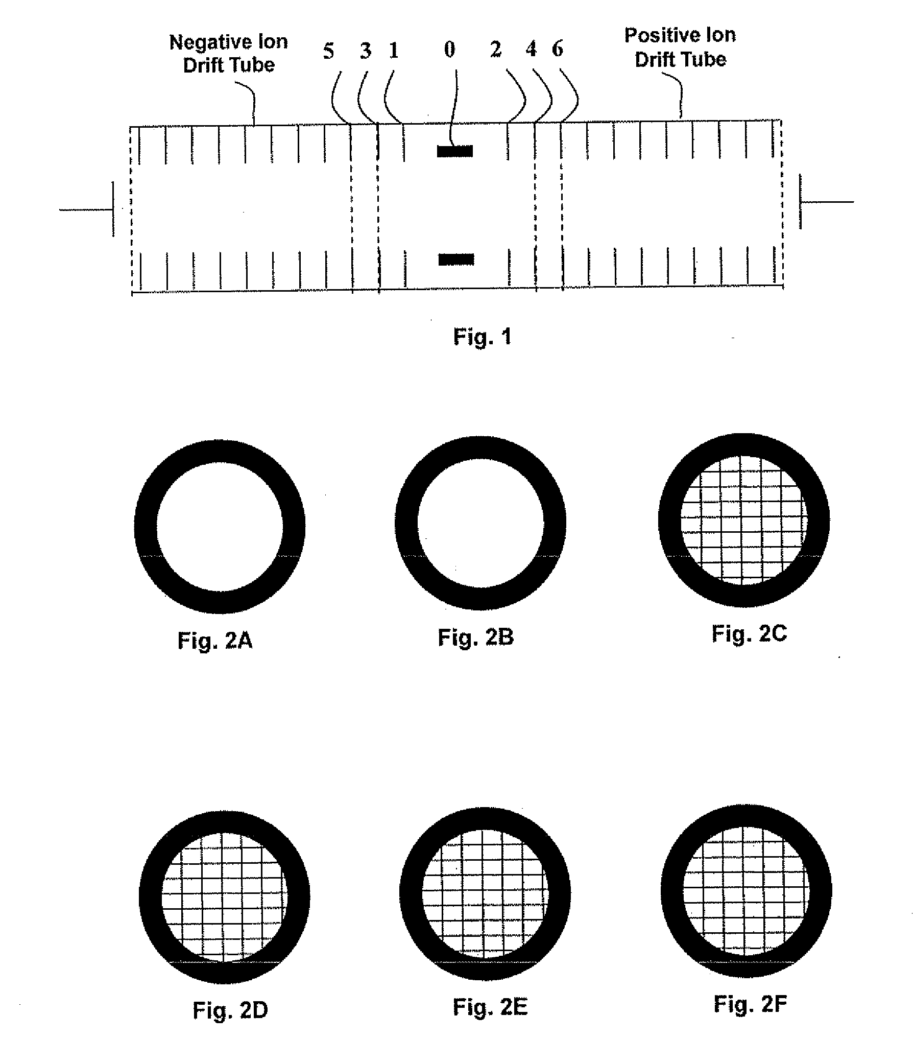
[0029]FIG. 1 shows an ion gate for positive and negative ions used in a dual IMS. The ion gate is provided with an ion source 0, a first gate electrode 1, a second gate electrode 2, a third gate electrode 3 and a fourth gate electrode 4. The second gate electrode 2 is located between the ion source 0 and the fourth gate electrode 4, and the first gate electrode 1 is located between the ion source 0 and the third gate electrode 3. Further, a fifth gate electrode 5 can be the initial part of a drift tube for detecting negative ions, and a sixth gate electrode 6 can be the initial part of a drift tube for detecting positive ions. With respect to the ion source 0, the first, third and fifth gate electrodes 1, 3, 5 are arranged in symmetry with the second, fourth and sixth gate electrodes 2, 4, 6.

[0030]The ion source 0 serves to ionize sample molecules. The ion source can be a radioactive isotope, laser and the like. Each of the first and second gate electrodes 1, 2 is a plate having a h...

second embodiment

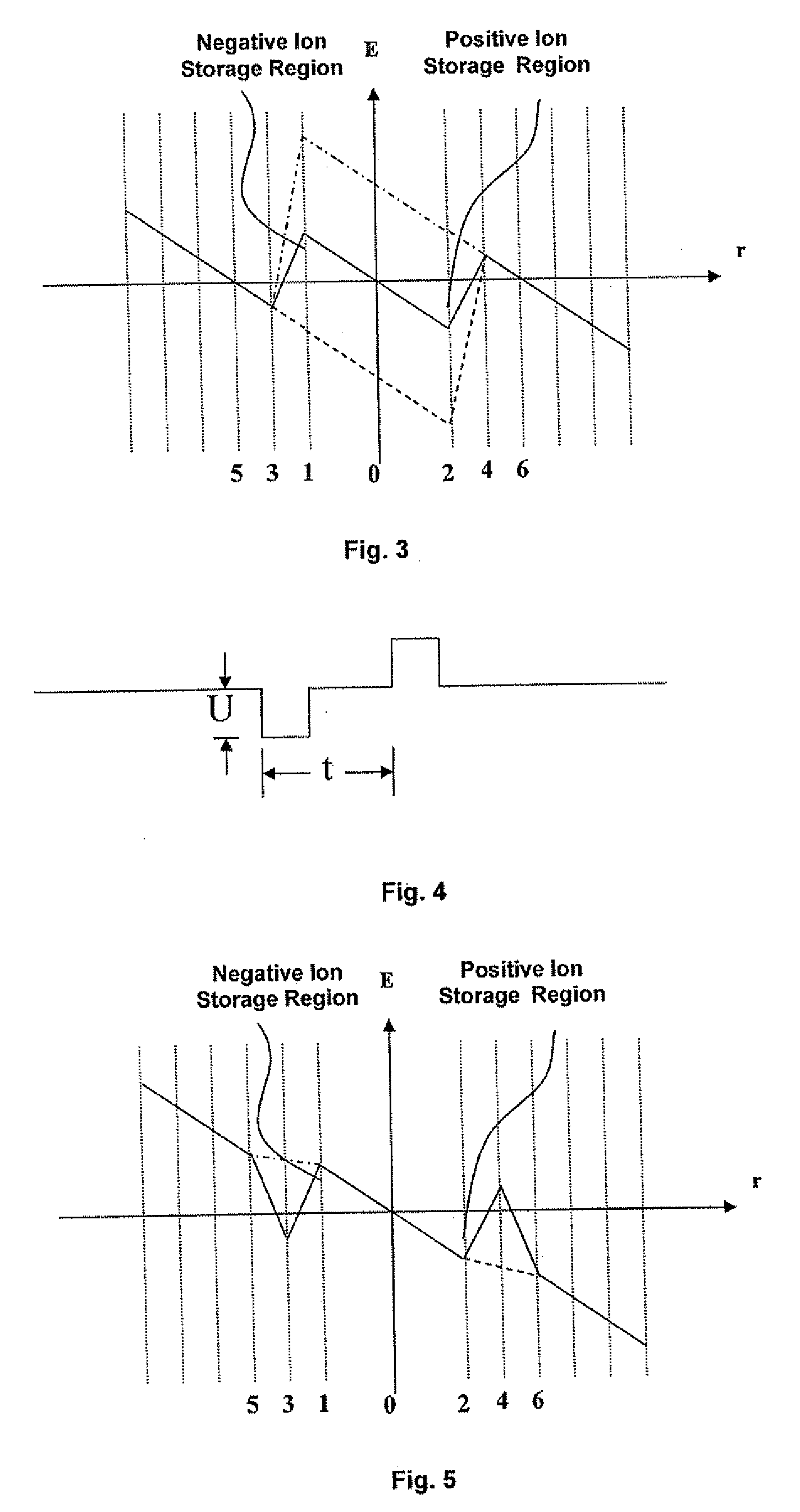
[0041]FIG. 5 is a schematic graph of the distribution of potentials along the tube axis during the ion storage and eduction according to the second embodiment of the present invention.

[0042]As shown in FIG. 5, according to the second embodiment of the present invention, the respective electrodes and the ion source are applied with voltages during the ion storage phase so that the potentials along the tube axis of the ion gate fulfill the relationship: the potential at the fifth gate electrode 5>the potential at the first gate electrode 1>the potential at the ion source 0>the potential at the third gate electrode 3, and accordingly a negative ion storage region for storing negative ions is formed adjacent to the first gate electrode 1; and the potential at the sixth gate electrode 6204, and accordingly a positive ion storage region for storing positive ions is formed adjacent to the second gate electrode 2.

[0043]During the phase of eduction of negative ion, a negative pulse is applie...

third embodiment

[0054]FIG. 6 is a schematic graph of the distribution of potentials along the tube axis during the ion storage and eduction according to the third embodiment of the present invention.

[0055]the respective electrodes and the ion source are applied with voltages during the ion storage phase so that the potentials along the tube axis of the ion gate fulfill the relationship: the potential at the first gate electrode 1>the potential at the fifth gate electrode 5=the potential at the ion source 0>the potential at the third gate electrode 3, and accordingly a negative ion storage region is formed adjacent to the first gate electrode 1; and the potential at the second gate electrode 20=the potential at the sixth gate electrode 64, and accordingly a positive ion storage region is formed adjacent to the second gate electrode 2.

[0056]During the phase of negative ion eduction, the negative ions are educed by controlling only the potential at the ion source 0, requiring a negative pulse having a...


PUM


Abstract

Disclosed is an ion gate for a dual IMS and method. The ion gate includes an ion source, a first gate electrode placed on one side of the ion source, a second gate electrode placed on the other side of the ion source, a third gate electrode placed on the side of the first gate electrode away from the ion source, a fourth gate electrode placed on the side of the second gate electrode away from the ion source, wherein during the ion storage, the potential at the position on the tube axis of the ion gate corresponding to the first gate electrode is different from the potentials at the positions on the tube axis corresponding to the ion source and the third gate electrode, and the potential at the position on the tube axis corresponding to the second gate electrode is different from the potentials at the positions on the tube axis corresponding to the ion source and the fourth gate electrode. According to the present invention, after sample gas enters the ion gates, charge exchange with reaction ions occurs between the first gate electrode and the second electrode, and positive and negative ions are continuously stored into the storage regions for the positive and negative ions. This leads to an improvement of utility rate of ions. Then, the ions are educed in a step-wise manner from the storage regions for the positive and negative ions by a simple control of a combination of the electrodes.

Description

BACKGROUND OF THE INVENTION[0001]1. Field of Invention[0002]The present invention relates to a field of inspection on explosives, drug and the like, and in particular to an ion gate used in a dual ion mobility spectrometer (IMS) and the method thereof.[0003]2. Description of Prior Art[0004]Generally, a dual IMS is primarily formed of an ion source, two drift tubes (TOF), a positive and negative ion reaction zone, a positive ion gate, a negative ion gate and two detectors. The simplest formation is such that the two drift tubes are located on the two sides of the reaction zone, respectively. The dual IMS differs from a common IMS in that the structure of the ion gate imposes a significant effect on the sensitivity of the instrument due to the necessity of positive and negative ion detection. As shown in Patent Document 1 (U.S. Pat. No. 4,445,038), two electrodes arranged in the front of the drift tubes for positive and negative ions, respectively, forms the gates for positive and neg...

Claims


Application Information

Patent Timeline
Patent Type & Authority Applications(United States)
IPC IPC(8): H01J49/02B01D59/44
CPCH01J3/04H01J49/061H01J49/004
Inventor PENG, HUAZHANG, QINGJUNLIN, JINLI, YUANJINGCHEN, ZHIQIANGMAO, SHAOJIDAI, ZHUDECAO, SHIPINGZHANG, ZHONGXIAZHANG, YANGTIANLIN, DEXUWANG, QINGHUAJUN, ZHANG QING
Owner NUCTECH CO LTD
Why Eureka
Try Eureka