Display device

a technology of display device and semiconductor device, which is applied in the direction of static indicating device, non-linear optics, instruments, etc., can solve the problems of large amount of electric power, low contrast ratio, and temporal fluctuation (a flicker) of display luminance or the like, so as to reduce the light emission luminance of backlight changes, reduce unevenness and flicker, and greatly improve image quality

Active Publication Date: 2010-04-29
SEMICON ENERGY LAB CO LTD
View PDF30 Cites 85 Cited by
  • Summary
  • Abstract
  • Description
  • Claims
  • Application Information

AI Technical Summary

Benefits of technology

[0095]According to one embodiment of the present invention, since a change in the light emission luminance of a backlight can be reduced in a portion related to the motion of an image, unevenness and flickers can be suppressed and image quality can be greatly improved. Alternatively, according to one embodiment of the present invention, since the light emission luminance of a backlight can be partly controlled, a contrast ratio can be increased. Alternatively, according to one embodiment of the present invention, the quality of a moving image can be improved by double-frame rate driving or black data insertion driving. Alternatively, according to one embodiment of the present invention, the viewing angle can be improved by multi-domain or a subpixel structure. Alternatively, according to one embodiment of the present invention, the response speed of a liquid crystal element can be made higher by overdrive. Alternatively, according to one embodiment of the present invention, power consumption can be reduced by increasing the efficiency of a backlight, for example. Alternatively, according to one embodiment of the present invention, a manufacturing cost can be reduced by optimizing a driver circuit, for example.

Problems solved by technology

A liquid crystal display device which is driven in a state physically or visually uniform without a partial change in the light emission luminance of the backlight consumes a large amount of electric power.
Further, since the amount of light leakage in the region with dark display is large, a contrast ratio decreases, which is a problem.
In the case where the light-emission luminance of the backlight is partly changed to be controlled, as pointed out in Patent Documents 1 and 2, temporal fluctuation (a flicker) in display luminance or the like becomes a problem.
This is mainly because accurate planar distribution of the light emission luminance with temporal fluctuation is difficult to obtain.

Method used


Image

  • Display device
  • Display device
  • Display device

Examples


embodiment 1

[0114]As Embodiment 1, an example of the structure of a display device or an example of a driving method of the display device will be described.

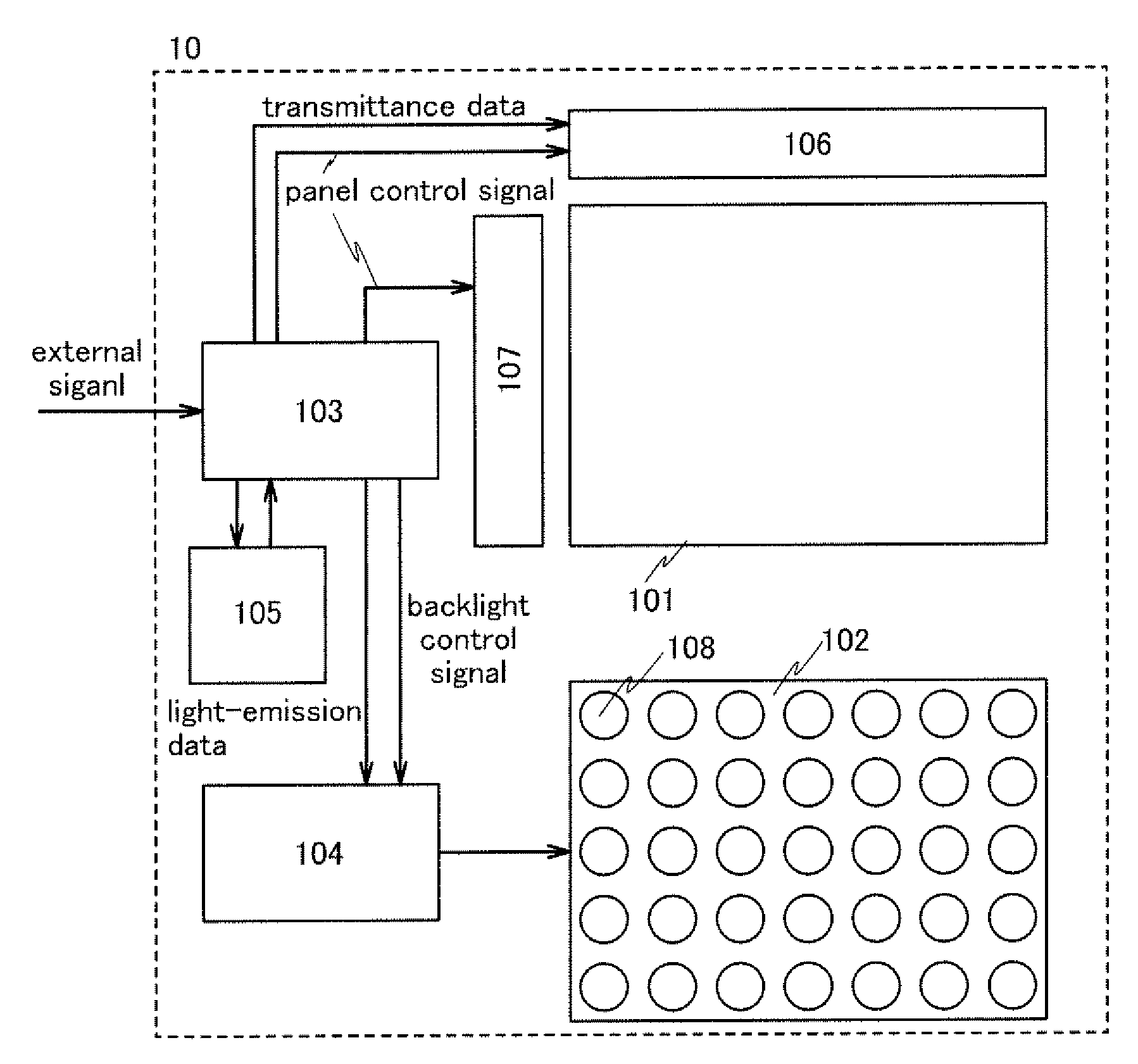
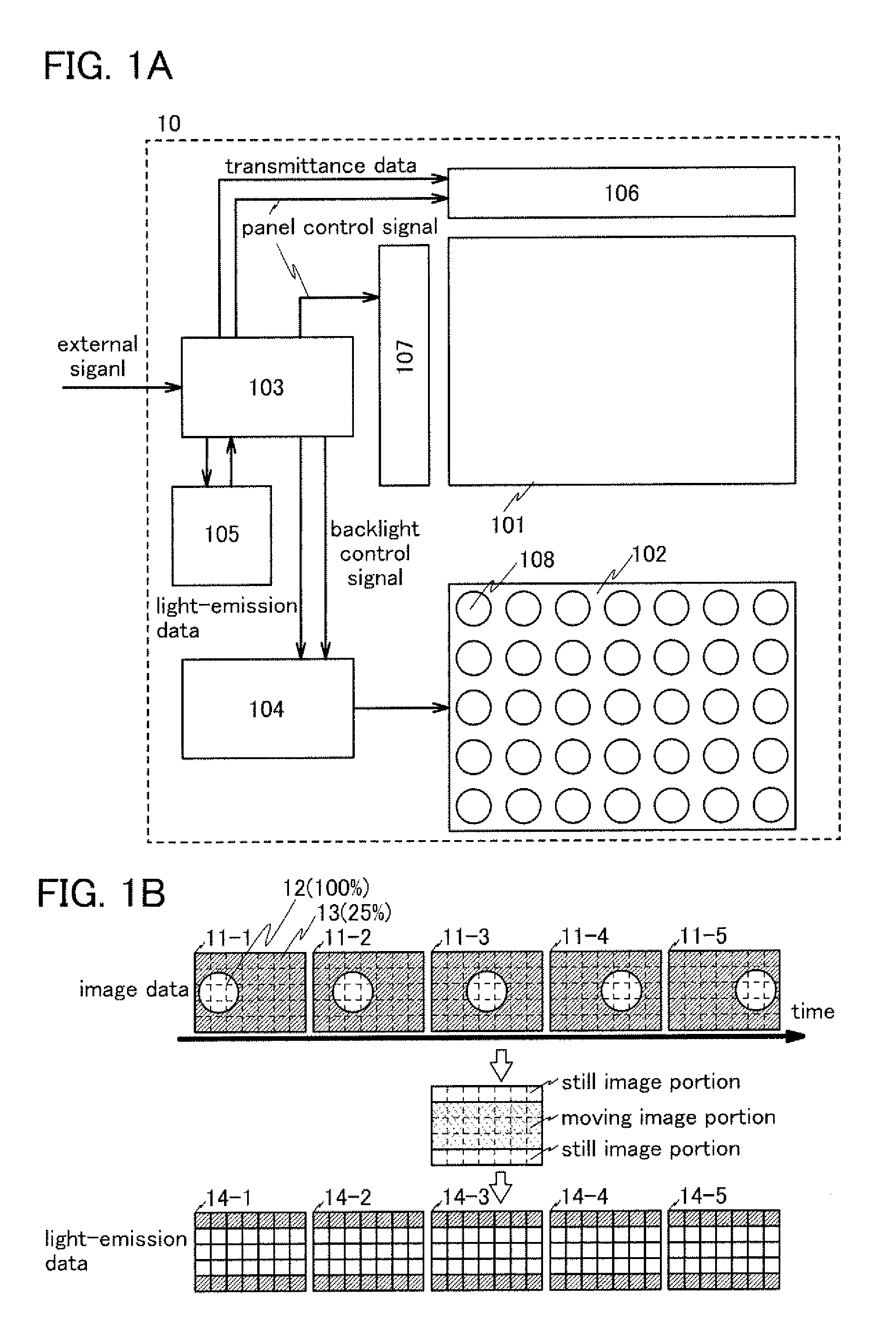
[0115]As shown in FIG. 1A, a display device 10 in this embodiment can include a pixel portion 101, a backlight 102, a panel controller 103, a backlight controller 104, and a memory 105. Note that the panel controller 103 and the backlight controller 104 may be formed using one chip. The pixel portion 101 may include a plurality of pixels. A source driver 106 and a gate driver 107 which are driver circuits of the pixel portion 101 can be provided in a peripheral portion of the pixel portion 101. Note that whether to provide all or part of each of the source driver 106 and gate driver 107 over the same substrate as the pixel portion 101 or over a different substrate from the pixel portion 101 can be selected. In the case where the driver circuits of the pixel portion 101 are provided over the same substrate as the pixel portion 101, the numbe...

embodiment 2

[0147]As Embodiment 2, another example of a structure of a display device and a driving method thereof will be described. In this embodiment, an example of a driving method in the case where motion compensation double frame-rate driving is employed in addition to the driving method described in Embodiment 1 will be described. Note that the motion compensation double frame-rate driving is to make the movement of a display object smooth by analyzing the movement of the display object from image data in a plurality of frames, generating image data that shows an intermediate state of the display object in the plurality of frames, and inserting the image data that shows the intermediate state as an interpolation image between the plurality of frames. By employing the motion compensation double frame-rate driving in addition to the driving method described in Embodiment 1, a display device which has an advantage of being able to display a smooth moving image in addition to the advantage d...

embodiment 3

[0155]As Embodiment 3, another example of a structure of a display device and a driving method thereof will be described. In this embodiment, an example of a driving method in the case where black data insertion driving is employed in addition to the driving method described in Embodiment 1 will be described. Note that the black data insertion driving is a driving method by which a period for displaying a black image is provided between display in one frame and display in the next frame so that afterimages due to hold driving are reduced and the quality of a moving image is improved. By employing the black data insertion driving in addition to the driving method described in Embodiment 1, a display device which has an advantage that the quality of a moving image is improved in addition to the advantage described in Embodiment 1 can be achieved. Note that as a method for displaying a black image, a variety of methods can be given. A variety of methods for displaying a black image can...


PUM


Abstract

It is an object to improve image quality in displaying a still image and a moving image by suppressing flickers, a display malfunction, or the like of a display device. A method for controlling the light emission state of a backlight is made different between a still image portion and a moving image portion included in an image to be displayed. In specific, the amount of light emission in the still image portion is made as small as possible in a corresponding divided region of the backlight, and the amount of light emission in the moving image portion is controlled so as not to be changed as much as possible in a corresponding divided region of the backlight.

Description

BACKGROUND OF THE INVENTION[0001]1. Field of the Invention[0002]The present invention relates to a display device or a semiconductor device. In specific, the present invention relates to a hold display device such as a liquid crystal display device. Further, the present invention relates to a method for driving a liquid crystal display device in which the light-emission luminance of a backlight is partly controlled. Furthermore, the present invention relates to an electronic device including the display device in its display portion.[0003]2. Description of the Related Art[0004]Liquid crystal display devices can be formed thinner and more lightly than display devices formed using cathode ray tubes (CRT). Further, the liquid crystal display devices have advantages such as low power consumption. Furthermore, as the liquid crystal display device, a variety of liquid crystal display devices can be used, for example, from small liquid crystal display devices whose diagonal sizes of displa...

Claims


Application Information

Patent Timeline
Patent Type & Authority Applications(United States)
IPC IPC(8): G09G3/36
CPCG09G3/2022G09G3/3426G09G3/3611G09G2310/061G09G2320/0233G09G2320/0247G09G2340/16G09G2320/062G09G2320/066G09G2320/068G09G2320/103G09G2320/106G09G2320/0252G02F1/133G09G3/36
Inventor YOSHIDA, YASUNORIKIMURA, HAJIME
Owner SEMICON ENERGY LAB CO LTD
Why Eureka
Try Eureka