Connection combination type optical film, liquid crystal panel, image display device, and liquid crystal display device

a technology of liquid crystal display device and combination type, which is applied in the direction of instruments, polarising elements, vehicle components, etc., can solve the problems of light leakage from the portion, and achieve the effects of preventing the increase of light leakage over time, easy shrinkage or deformation, and improving durability

Inactive Publication Date: 2010-04-29
NITTO DENKO CORP
View PDF14 Cites 25 Cited by
  • Summary
  • Abstract
  • Description
  • Claims
  • Application Information

AI Technical Summary

Benefits of technology

[0017]In the combined optical film of the invention, a plurality of optical films abut against each other and are combined with a transparent connection film to which at least one side of the optical films combined is adhered through a pressure-sensitive adhesive layer or an adhesive layer. The combination optical films are joined by the transparent connection film. In the resulting combined optical film, the transparent connection film prevents the gap between the end faces of the optical films from widening over time so that an increase in light leakage over time can be prevented.
[0018]The combined optical film of the invention may be placed on the upper side (viewer side) of a liquid crystal cell and / or the lower side (backlight side) of a liquid crystal cell in a liquid crystal display device. The placement on the lower side (backlight side) is preferred, because the end faces of the optical films on the lower side are relatively hard to see.
[0019]In a liquid crystal display device, polarizing plates (or polarizers), which are optical films, are placed on the upper side and the lower side of a liquid crystal cell in such a manner that their absorption axes are orthogonal to each other. The polarizing plate (or polarizer) placed on the lower side is close to a backlight and therefore relatively easily undergoes shrinkage or deformation due to the heat from a backlight, which means that the gap between the polarizing plates can become wider over time on the lower side than on the upper side. Therefore, the combined optical film is required to have thermal durability. Concerning such durability, the combined optical film may be placed on the lower side of a liquid crystal cell in such a manner that the transparent connection film is placed on the backlight side so that the durability can be improved. In addition, the transparent connection film placed on the backlight side may be made of a thermoplastic resin with a water-vapor permeability of 100 g / m2 per 24 hours or less so that the durability can be further improved.
[0020]In a more preferred embodiment of the invention, the combined optical film includes: a plurality of polarizing plates each having at least one end face and including a polarizer and a transparent protective film placed on one or both sides of the polarizer, wherein the end faces abut against each other; and a transparent connection film that is adhered to at least one side of each of the polarizing plates through a pressure-sensitive adhesive layer or an adhesive layer so that the polarizing plates are joined by the transparent connection film. This structure is characterized by including the polarizing plates as the optical films. Preferably, the polarizing plates is less likely to undergo dimensional change over time than the polarizer alone so that the gap between the end faces abutting against each other can be less likely to become wider over time. In addition, the polarizing plate including the polarizer and the transparent protective films placed on both side of the polarizer is preferred, because it has higher mechanical strength and is less likely to undergo dimensional change over time than the polarizing plate including the polarizer and the transparent protective film placed on one side of the polarizer.
[0021]In a more preferred embodiment, the combined optical film includes: a plurality of polarizing plates each having at least one end face and including a polarizer and a transparent protective film placed on one or both sides of the polarizer, wherein the end faces abut against each other; and a transparent connection film that is adhered to at least one side of each of the polarizing plates through a pressure-sensitive adhesive layer so that the polarizing plates are joined by the transparent connection film. This structure is characterized by including the polarizing plates as the optical films and including the pressure-sensitive adhesive layer with which the transparent connection film is adhered. Preferably, the polarizing plates is less likely to undergo dimensional change over time than the polarizer alone so that the gap between the end faces abutting against each other can be less likely to become wider over time. Preferably, the pressure-sensitive adhesive can have a lower viscosity than that of the adhesive so that it can be less likely to intrude or cannot intrude into the gap between the end faces abutting against each other than the adhesive. In addition, the polarizing plate including the polarizer and the transparent protective films placed on both side of the polarizer is preferred, because it has higher mechanical strength and is less likely to undergo dimensional change over time than the polarizing plate including the polarizer and the transparent protective film placed on one side of the polarizer. In view of durability over time during use, therefore, it is particularly preferred to use the polarizing plate including the polarizer and the transparent protective films placed on both sides of the polarizer and to use the pressure-sensitive adhesive which is less likely to intrude into the gap between the end faces abutting against each other than the adhesive.

Problems solved by technology

Therefore, the portion of the end faces of liquid crystal displays butted against one another has a problem in which light can leak from the portion to from a light line on the front face of the liquid crystal displays.

Method used


Image

  • Connection combination type optical film, liquid crystal panel, image display device, and liquid crystal display device
  • Connection combination type optical film, liquid crystal panel, image display device, and liquid crystal display device
  • Connection combination type optical film, liquid crystal panel, image display device, and liquid crystal display device

Examples


example 1

Preparation of Combined Optical Film

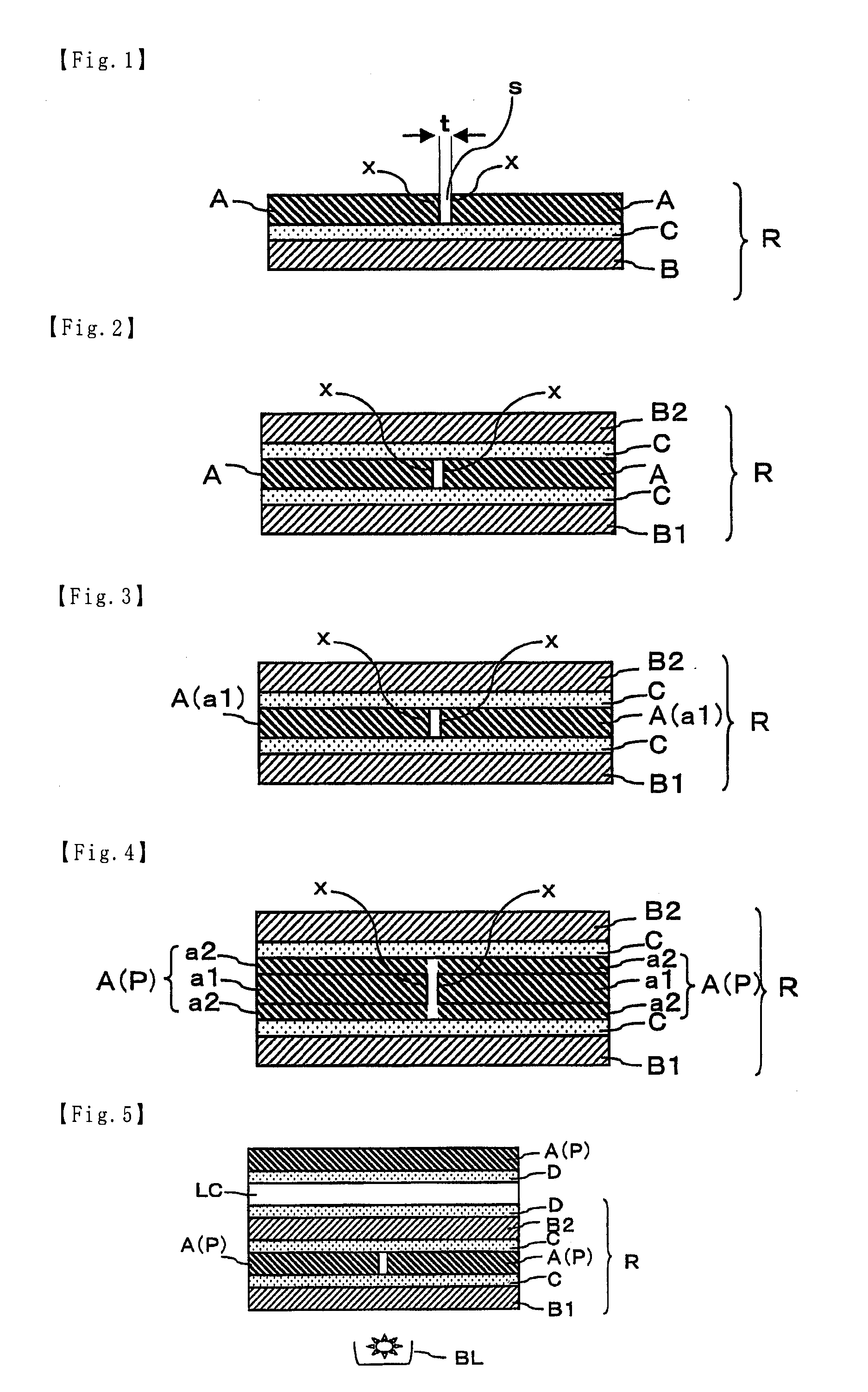
[0142]The shaped end faces (vertical end faces) of the polarizing plates were allowed to abut against each other so that the polarizing plates could be combined. The transparent connection film (Z-TAC) was adhered with the pressure-sensitive adhesive to one side of the polarizing plates to be combined, and the transparent connection film (NOR) was adhered with the pressure-sensitive adhesive to the other side of the polarizing plates to be combined, so that a combined optical film was prepared.

[0143]Preparation of Liquid Crystal Panel

[0144]The resulting combined optical film was adhered with the pressure-sensitive adhesive layer to the lower side (backlight side) of the liquid crystal cell in such a manner that the transparent connection film (Z-TAC) was placed on the liquid crystal cell side. The combined optical film had a gap s with a width t of 2.9 μm between the end faces abutting against each other.

[0145]A retardation layer-carrying polarizi...

example 2

Preparation of Combined Optical Film

[0146]A combined optical film was prepared using the process of Example 1, except that the transparent connection film (TD-TAC) was used in place of the transparent connection film (NOR).

[0147]Preparation of Liquid Crystal Panel

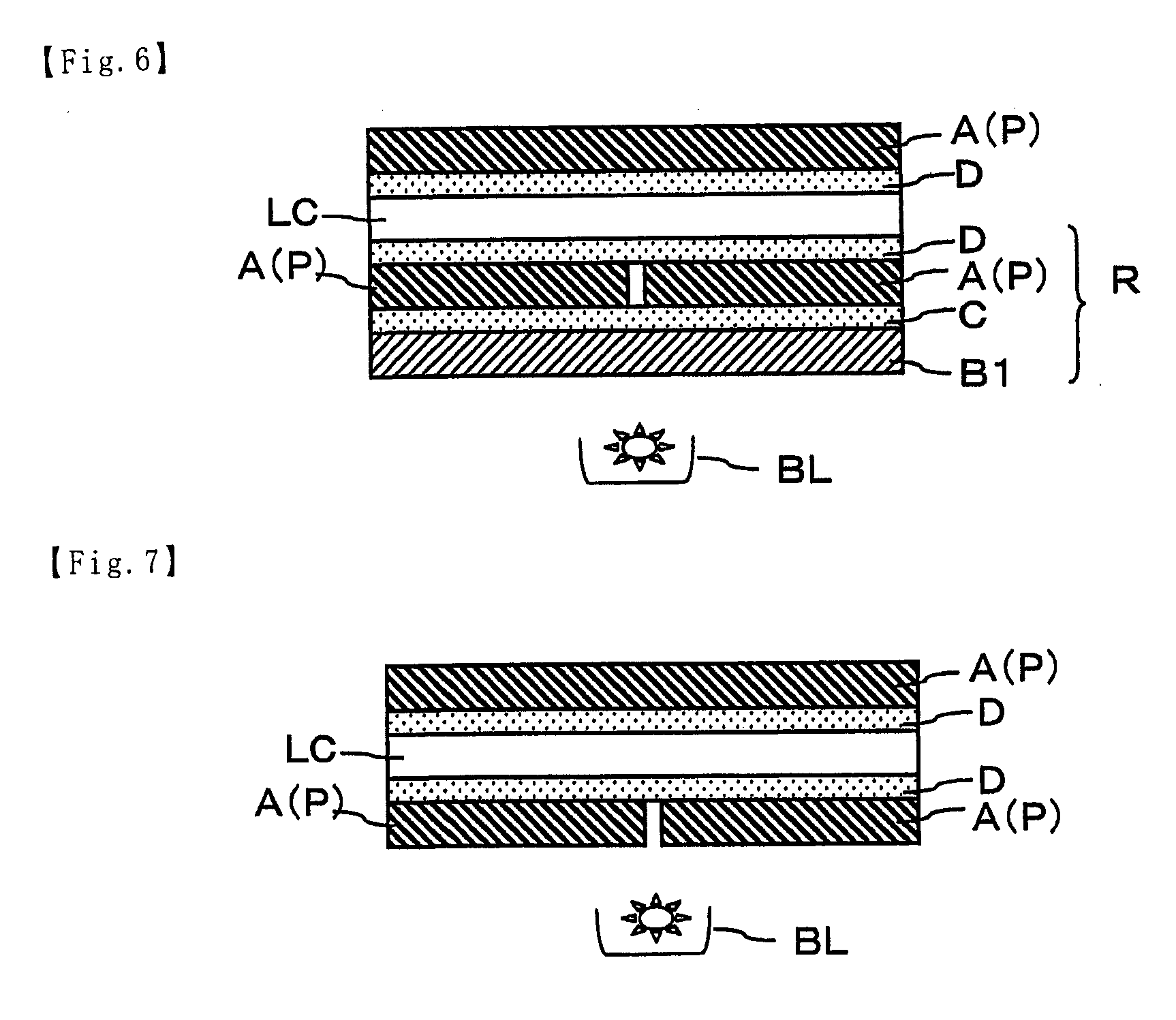
[0148]A liquid crystal panel was prepared using the process of Example 1, except that the resulting combined optical film was placed on the lower side of the liquid crystal cell. At this time, the combined optical film had a gap s with a width t of 2.7 μm between the end faces of the combined optical films.

example 3

Preparation of Combined Optical Film

[0149]A combined optical film was prepared using the process of Example 1, except that the transparent connection film (TD-TAC) was adhered to only one side of the combined polarizing plates.

[0150]Preparation of Liquid Crystal Panel

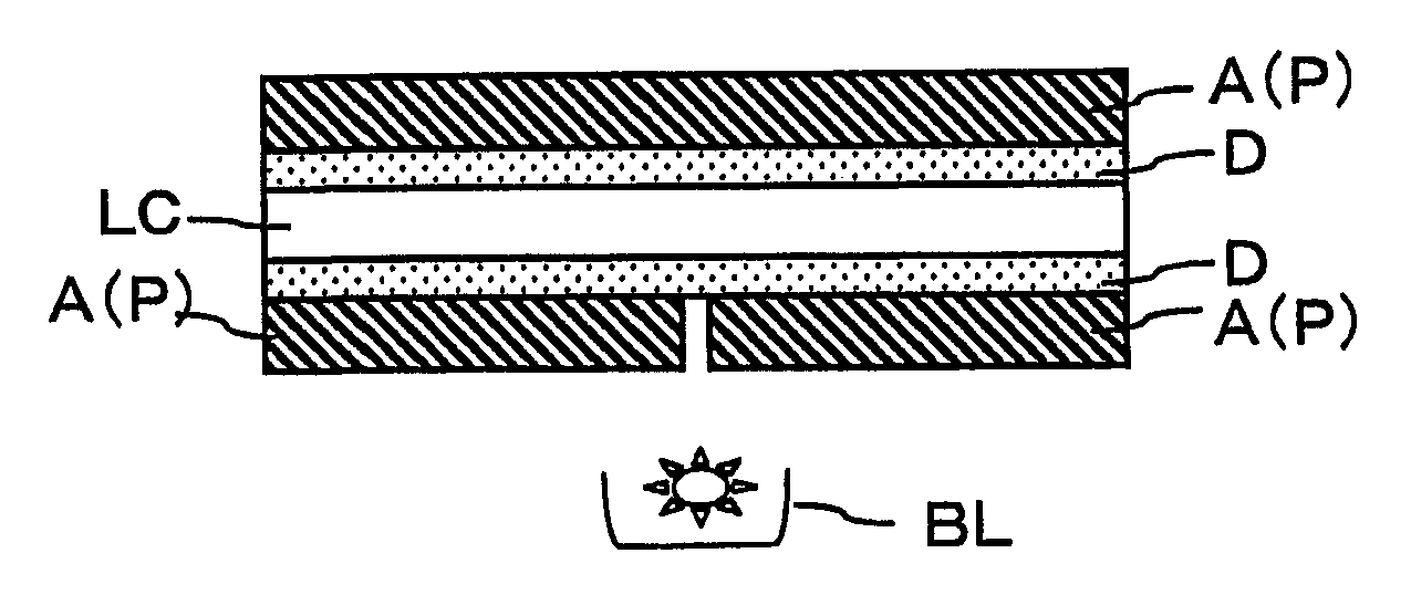
[0151]A liquid crystal panel was prepared using the process of Example 1, except that the resulting combined optical film was placed on the lower side of the liquid crystal cell and that the transparent connection film-free side was adhered to the liquid crystal cell with the pressure-sensitive adhesive layer. At this time, the combined optical film had a gap s with a width t of 2.5 μm between the end faces of the combined optical films.


PUM

PropertyMeasurementUnit
lengthaaaaaaaaaa
lengthaaaaaaaaaa
sizesaaaaaaaaaa

Abstract

An object of the invention is to prevent light leakage over time in a combined optical film including a plurality of optical films whose end faces are allowed to abut against each other. The invention is directed to a combined optical film, including: a plurality of optical films each having at least one end face, wherein the end faces abut against each other; and a transparent connection film that is adhered to at least one side of each of the optical films through a pressure-sensitive adhesive layer or an adhesive layer so that the optical films are joined by the transparent connection film.

Description

TECHNICAL FIELD[0001]The invention relates to a combined optical film including a plurality of optical films whose end faces are allowed to abut against each other. The invention also relates to an image display such as a liquid crystal display, an organic electroluminescence (EL) display and a plasma display panel (PDP), using the combined optical film.[0002]Examples of the optical film include a polarizer and a polarizing plate including a polarizer and a protective film placed on one or both sides of the polarizer. Examples of the optical film other than the polarizer and the polarizing plate include a retardation plate, an optical compensation film, and a brightness enhancement film. One or more of these films may be used alone or in combination.BACKGROUND ART[0003]Image displays such as liquid crystal displays for use in televisions, personal computers or the like use optical films such as polarizing plates. As the size of televisions or the like has grown in recent years, larg...

Claims


Application Information

Patent Timeline
Patent Type & Authority Applications(United States)
IPC IPC(8): G02F1/1335G02B27/00G02F1/1333
CPCG02F2202/28G02F1/133528G02B5/30G02F1/1335
Inventor YAMADA, TAKU
Owner NITTO DENKO CORP
Why Eureka
Try Eureka