X-ray diagnosis apparatus and image processing apparatus

a diagnosis apparatus and image processing technology, applied in the field of x-ray diagnosis apparatus and image processing apparatus, can solve the problem that the x-ray image that ensures the visibility of treatment equipment, such as a stent, cannot be displayed at the time of execution of vascular intervention treatment performed with reference to an x-ray imag

Active Publication Date: 2010-04-29
TOSHIBA MEDICAL SYST CORP
View PDF30 Cites 48 Cited by
  • Summary
  • Abstract
  • Description
  • Claims
  • Application Information

AI Technical Summary

Benefits of technology

[0018]For this reason, the present invention has been made to solve the problems of the conventional technology described above, and an object of the present invention is to provide an X-ray diagnosis apparatus and an image processing apparatus that can instantly display an X-ray image that ensures visibility of treatment equipment at the time of execution of a treatment performed with reference to an X-ray image.

Problems solved by technology

The conventional technology described above has a problem that an X-ray image that ensures visibility of treatment equipment, such as a stent, cannot be instantly displayed at the time of execution of vascular intervention treatment performed with reference to an X-ray image.
Similarly to the case of performing vascular intervention treatment, any case of treatment performed by a doctor referring to an X-ray image with the use of treatment equipment (for example, rotablator) attached with X-ray impermeable marker and arranged in a treatment portion that moves continuously due to throbs has a problem of incapability of instantly displaying an X-ray image that ensures visibility of the treatment equipment, even by using the conventional technology described above.

Method used


Image

  • X-ray diagnosis apparatus and image processing apparatus
  • X-ray diagnosis apparatus and image processing apparatus
  • X-ray diagnosis apparatus and image processing apparatus

Examples


first embodiment

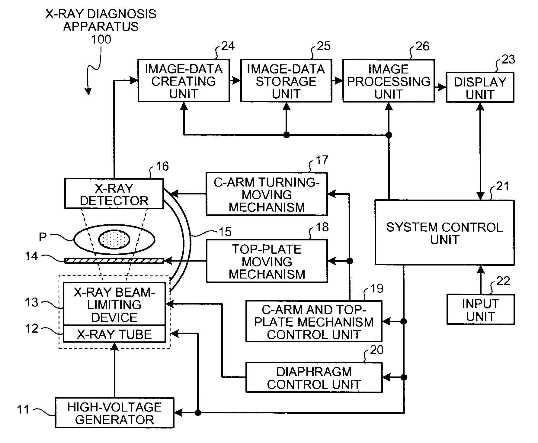
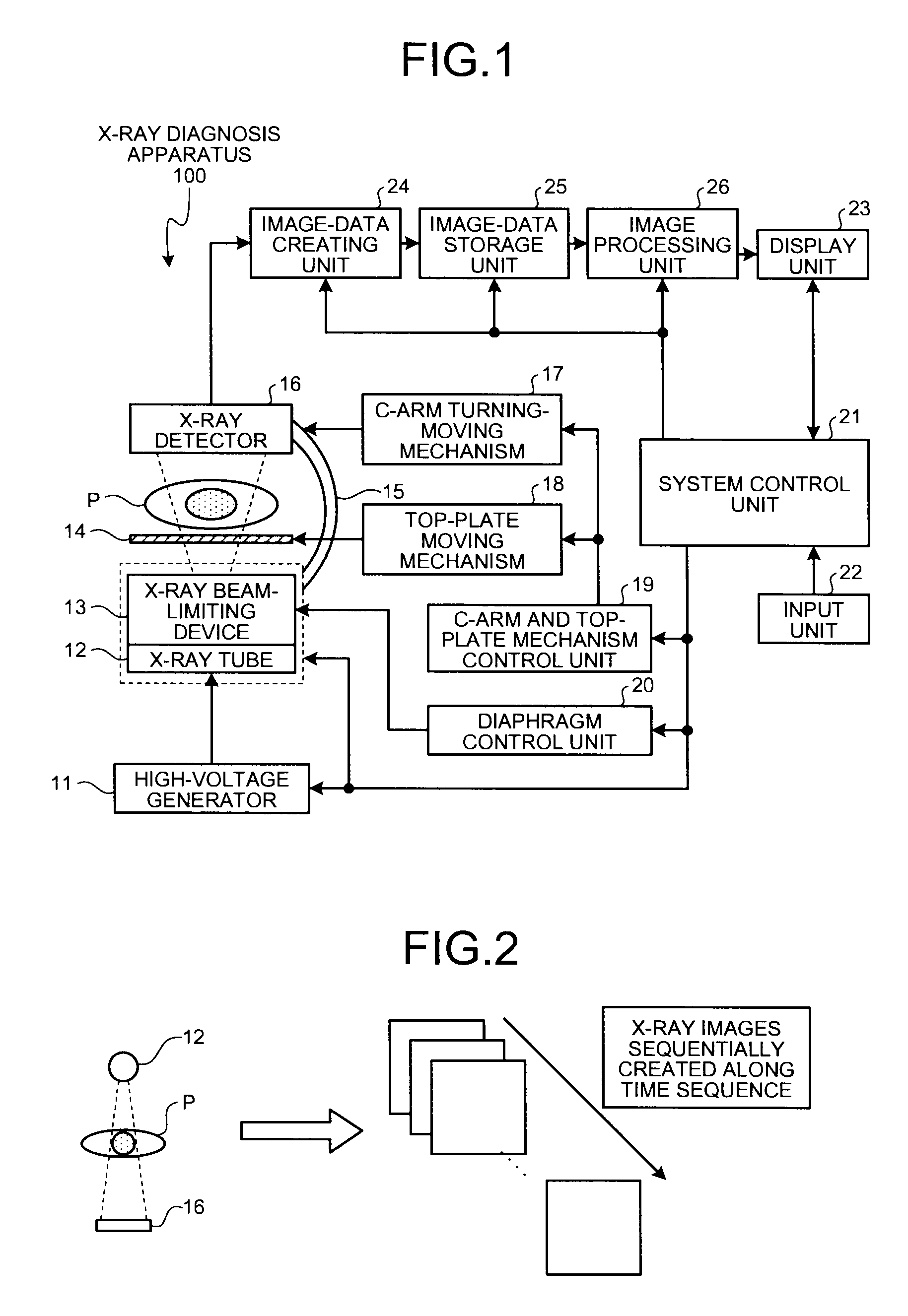
[0046]As shown in FIG. 1, the X-ray diagnosis apparatus 100 includes a high-voltage generator 11, an X-ray tube 12, an X-ray beam-limiting device 13, a top plate 14, a C-arm 15, an X-ray detector 16, a C-arm turning-moving mechanism 17, a top-plate moving mechanism 18, a C-arm and top-plate mechanism control unit 19, a diaphragm control unit 20, a system control unit 21, an input unit 22, a display unit 23, an image-data creating unit 24, an image-data storage unit 25, and an image processing unit 26.

[0047]The high-voltage generator 11 is a device that generates a high voltage and supplies the generated high voltage to the X-ray tube 12; and the X-ray tube 12 is a device that generates X-rays by using a high voltage supplied by the high-voltage generator 11. In other words, the high-voltage generator 11 controls an adjustment in X-ray dosage to be radiated onto a subject P, and ON / OFF of X-ray radiation to the subject P, by regulating a voltage supplied to the X-ray tube 12.

[0048]T...

modification 1

(Modification 1)

[0109]As shown in FIG. 9A, in the X-ray diagnosis apparatus 100 according to the first embodiment, a sensor 27 for detecting a movement of the top plate 14 is attached to the top plate 14 on which the subject P lies, so that the system control unit 21 performs control of suspending display of an image for display during a period in which a movement (the amount of movement) of the top late 14 (i.e., the couch on which the top plate 14 is arranged) detected by the sensor 27 is equal to or larger than a threshold.

[0110]Otherwise, in the X-ray diagnosis apparatus 100 according to the first embodiment, as shown in FIG. 9B, when the amount of movement of coordinates of the stent markers in a k+1th frame currently detected by the marker-coordinate detecting unit 26a from already-detected coordinates of the stent markers in a k-th frame is equal to or larger than a threshold, the system control unit 21 performs control of suspending display of an image for display. When disp...

modification 2

(Modification 2)

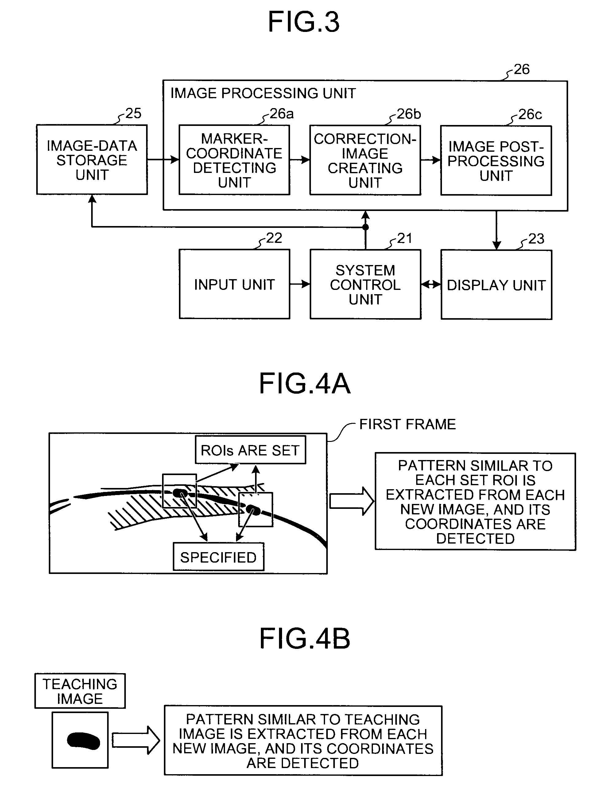
[0112]In the X-ray diagnosis apparatus 100 according to the first embodiment, as shown in FIG. 10A, when the stent markers are not extracted on a new image (the k+1th frame), the system control unit 21 stops correction-image creating processing, and continuously displays an image for display created from the previous X-ray image (the k-the frame).

[0113]Usually, during fluroscopic imaging, 15 to 30 frames of X-ray images are created for one second. When coordinates of the stent markers are not detected on a new image, the system control unit 21 continuously displays an image for display created from the previous frame. When coordinates of the stent markers are then detected again on a new image, the system control unit 21 performs control of displaying an image for display by executing correction-image creating processing. Accordingly, images for display on which the stent portion matches up can be displayed as a moving image, while not giving uncomfortable feeling to...


PUM


Abstract

A marker-coordinate detecting unit detects coordinates of a stent marker on a new image when the new image is stored in an image-data storage unit; and then a correction-image creating unit creates a correction image from the new image through, for example, image transformation processing, so as to match up the detected coordinates with reference coordinates that are coordinates of the stent marker already detected by the marker-coordinate detecting unit in a first frame. An image post-processing unit then creates an image for display by performing post-processing on the correction image created by the correction-image creating unit, the post-processing including high-frequency noise reduction filtering-processing, low-frequency component removal filtering-processing, and logarithmic-image creating processing; and then a system control unit performs control of displaying a moving image of an enlarged image of a set region that is set in the image for display, together with an original image.

Description

CROSS-REFERENCE TO RELATED APPLICATIONS[0001]This application is based upon and claims the benefit of priority from the prior Japanese Patent Application No. 2008-275348, filed on Oct. 27, 2008; the entire contents of which are incorporated herein by reference.BACKGROUND OF THE INVENTION[0002]1. Field of the Invention[0003]The present invention relates to an X-ray diagnosis apparatus and an image processing apparatus.[0004]2. Description of the Related Art[0005]A treatment method called vascular intervention treatment has been conventionally performed on a stenosed portion occurring in a blood vessel caused by, for example, a thrombus.[0006]According to vascular intervention treatment, a balloon-tip catheter is inserted by a doctor up to a stenosed portion. A liquid is then injected into the balloon through the catheter, so that the balloon is expanded, as a result, the stenosed portion is mechanically expanded. After the liquid in the balloon is sucked, the balloon-tip catheter is ...

Claims


Application Information

Patent Timeline
Patent Type & Authority Applications(United States)
IPC IPC(8): G06K9/62
CPCA61B5/0402A61B6/12A61B6/4441A61B6/481A61B6/504G06T7/2033G06T2207/30204G06T2207/20104G06T2207/20164G06T2207/30021G06T2207/30048G06T2207/30052G06T2207/30101G06T2207/10121G06T7/246G06T7/11A61B5/318G06T5/50A61B6/461A61B6/486A61B6/5205G06T7/0012G06T2207/10116
Inventor SAKAGUCHI, TAKUYANAMBU, KYOJIROTAKEMOTO, HISATO
Owner TOSHIBA MEDICAL SYST CORP
Why Eureka
Try Eureka