Device for controlling the pitch of fan blades of a turboprop

Inactive Publication Date: 2010-04-29
SN DETUDE & DE CONSTR DE MOTEURS DAVIATION S N E C M A
View PDF6 Cites 12 Cited by
  • Summary
  • Abstract
  • Description
  • Claims
  • Application Information

AI Technical Summary

Benefits of technology

[0006]The present invention thus has a main object of mitigating such drawbacks by proposing a device for c

Problems solved by technology

The weight of the contr

Method used


Image

  • Device for controlling the pitch of fan blades of a turboprop
  • Device for controlling the pitch of fan blades of a turboprop
  • Device for controlling the pitch of fan blades of a turboprop

Examples


Example

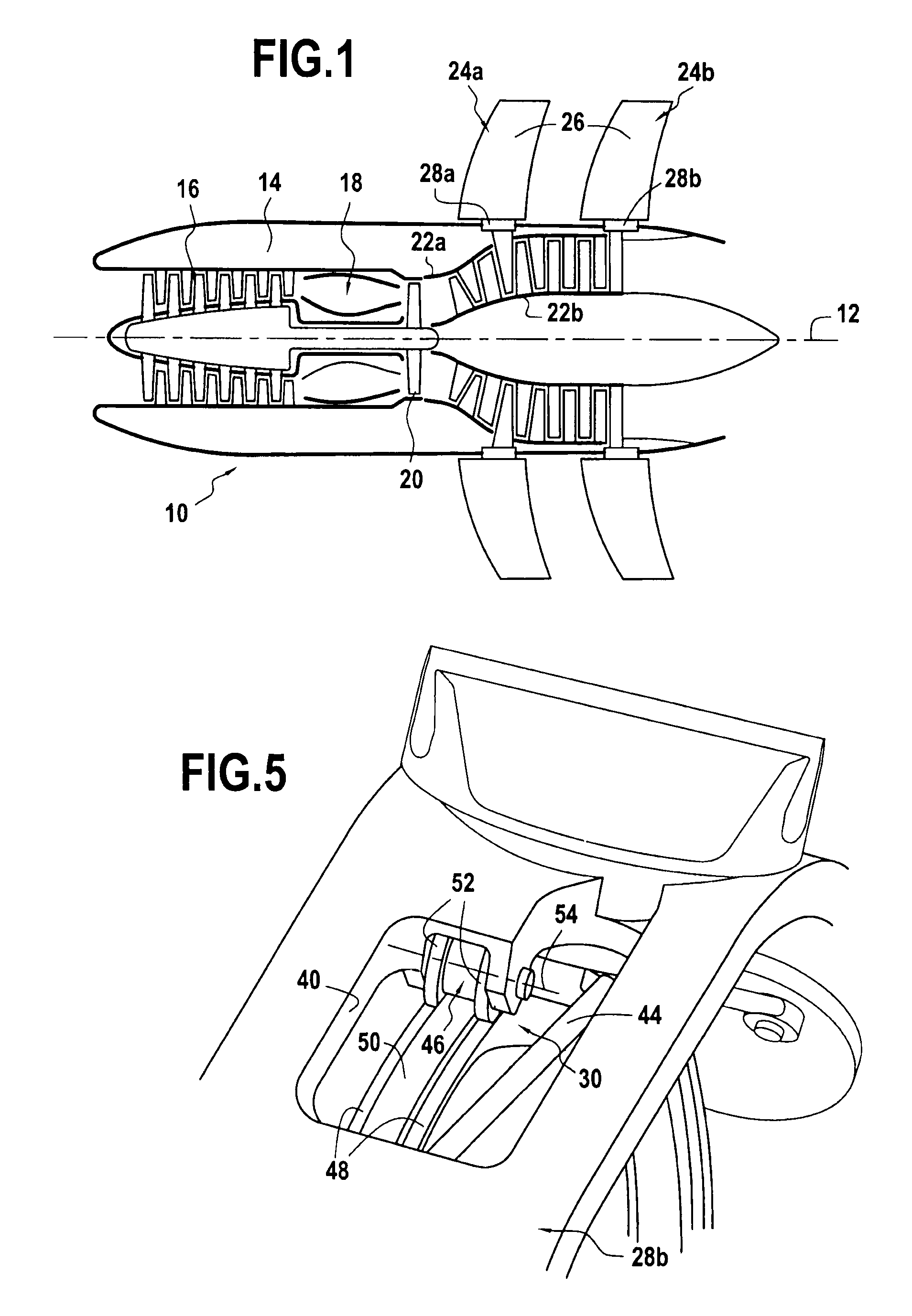
[0022]FIG. 1 is a highly diagrammatic view showing an embodiment of an airplane turboprop of the type having two propellers.

[0023]Such a turbojet is itself known and is therefore not described in detail. The turboprop 10 comprises in particular a longitudinal axis 12 and an annular nacelle 14 disposed coaxially around the longitudinal axis. The turboprop 10 also comprises, from upstream to downstream: a compressor 16; a combustion chamber 18; and a turbine 20 having two contrarotating rotors 22a and 22b, these various elements all being disposed coaxially about the longitudinal axis 12 of the turboprop.

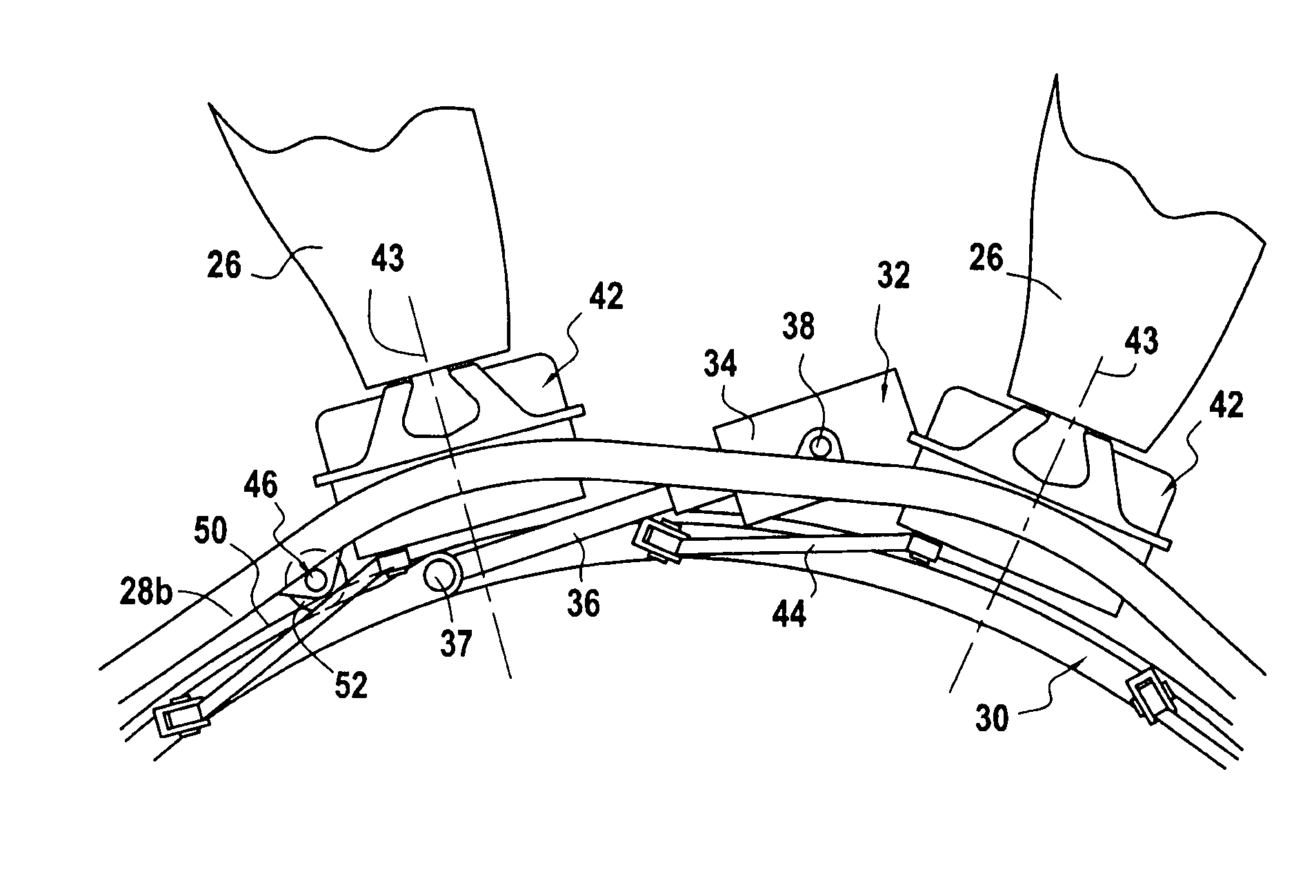
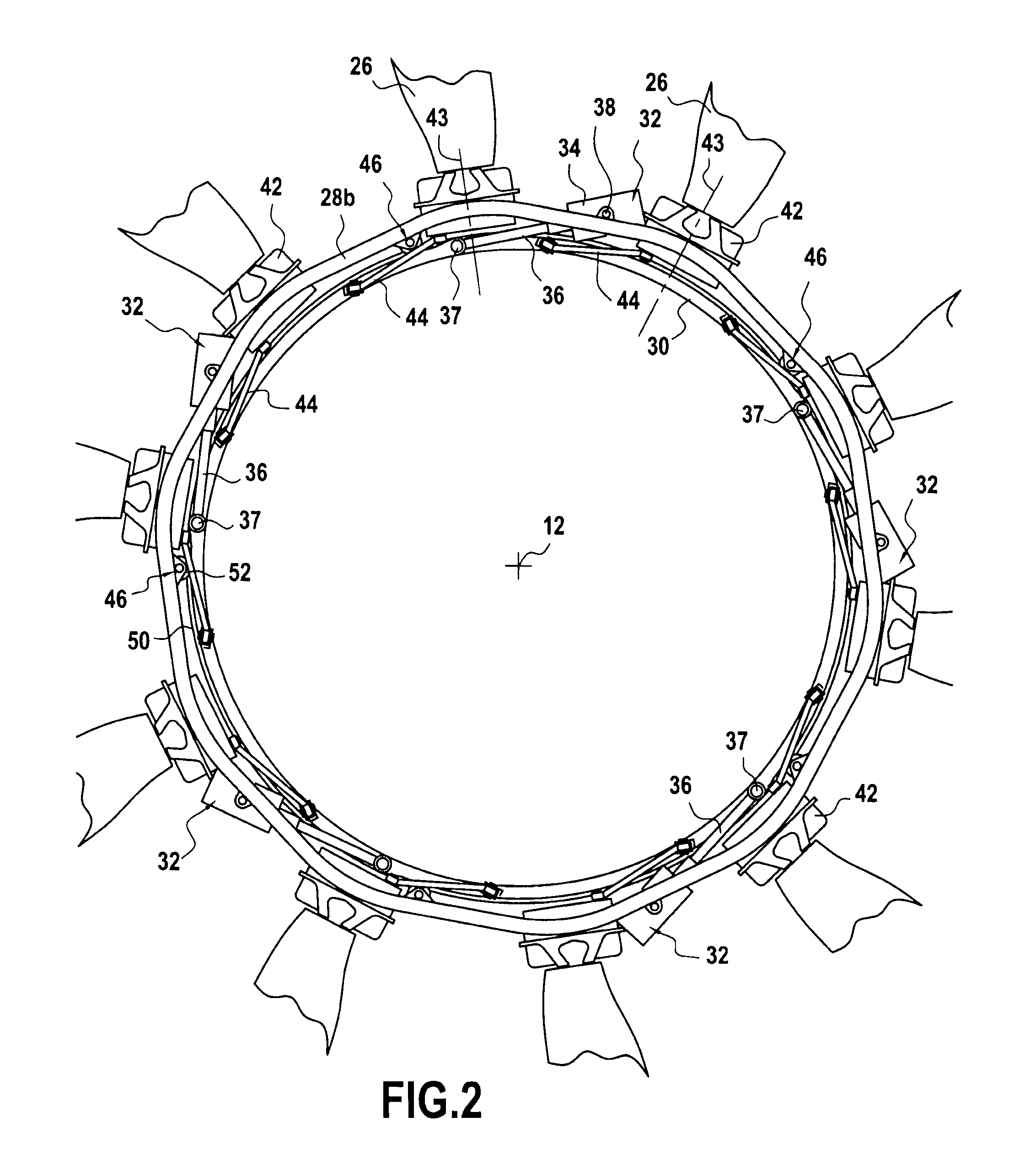
[0024]The turboprop 10 also comprises an upstream set 24a and a downstream set 24b of fan blades 26 of adjustable pitch. The fan blades 26 in each set 24a, 24b are, more precisely, mounted on a respective rotary ring 28a, 28b in the form of an annular platform centered on the longitudinal axis 12 of the turboprop. The fan blades in each set are regularly spaced apart circumferentially...


PUM


Abstract

The invention relates to a device for controlling the pitch of fan blades of a turboprop. The device includes at least at least one set of adjustable pitch fan blades secured to rotate with a rotary ring centered on a longitudinal axis and mechanically connected to a turbine rotor. Each blade of the set is coupled for pitch-adjustment purposes with a synchronization ring centered on the longitudinal axis, the synchronization ring being suitable for pivoting about the longitudinal axis relative to the rotary ring under drive from actuators carried by the rotary ring and each having a respective axis extending in a direction that is substantially tangential to the synchronization ring.

Description

BACKGROUND OF THE INVENTION[0001]The present invention relates to the general field of turboprops having at least one set of fan blades that are adjustable in pitch. The invention relates more particularly to controlling the pitch of fan blades of an airplane turboprop having two propellers.[0002]In known manner, an airplane turboprop having two propellers comprises a turbine with two contrarotating rotors each driving a non-ducted set of fan blades. For example, reference can be made to document GB 2 129 502 which describes various embodiments of such a turboprop.[0003]In that type of turboprop, the pitch of the fan blades in each set constitutes one of the parameters that enables the thrust of the turboprop to be controlled (this can also be referred to as adjusting the orientation of the blades). Various devices already exist for adjusting the pitch of fan blades in a given set. For example, one known system consists in using an actuator that is arranged axially in the inside spa...

Claims


Application Information

Patent Timeline
IPC IPC(8): F01D1/24F01D7/00
CPCF01D7/00F02K3/025Y02T50/671F05D2260/79F05D2260/74F05D2260/56F05D2220/325Y02T50/60
Inventor CHARIER, GILLES ALAINGALLET, FRANCOISBALK, WOUTER
Owner SN DETUDE & DE CONSTR DE MOTEURS DAVIATION S N E C M A
Why Eureka
Try Eureka