
Rf signal sampling apparatus and method

Inactive Publication Date: 2010-04-29
QIAN XUECHENG
View PDF3 Cites 5 Cited by
  • Summary
  • Abstract
  • Description
  • Claims
  • Application Information

AI Technical Summary

Benefits of technology

[0015]Compared with prior art documents, the RF signal sampling apparatus and method of the invention may implement high frequency selectivity by using simple discrete filters. The overall circuit structure is simpleer, requiring fewer clock signals, and thus reducing the complexity and power consumption.

Problems solved by technology

Furthermore, the RF filter has a limited suppression over the out-of-band (OOB) interference.
However, because the RF receiver requires a high sampling frequency, its power consumption is usually high.
Typically, more circuits operating at high frequency (HF) will result in higher power consumption for the receiver.
This is the main reason why conventional RF sampling receivers have not been applied widely so far.
However, the circuitry is very complex in comparison with conventional samplers.
However, the spectral notch formed by the FIR filter is not wide enough, and so the down-sampling factor cannot be too large.
However, there is a need for a very complex circuit and plenty of clock signals, which will increase the cost and power consumption for the circuit.

Method used


Image

  • Rf signal sampling apparatus and method
  • Rf signal sampling apparatus and method
  • Rf signal sampling apparatus and method

Examples


Embodiment Construction

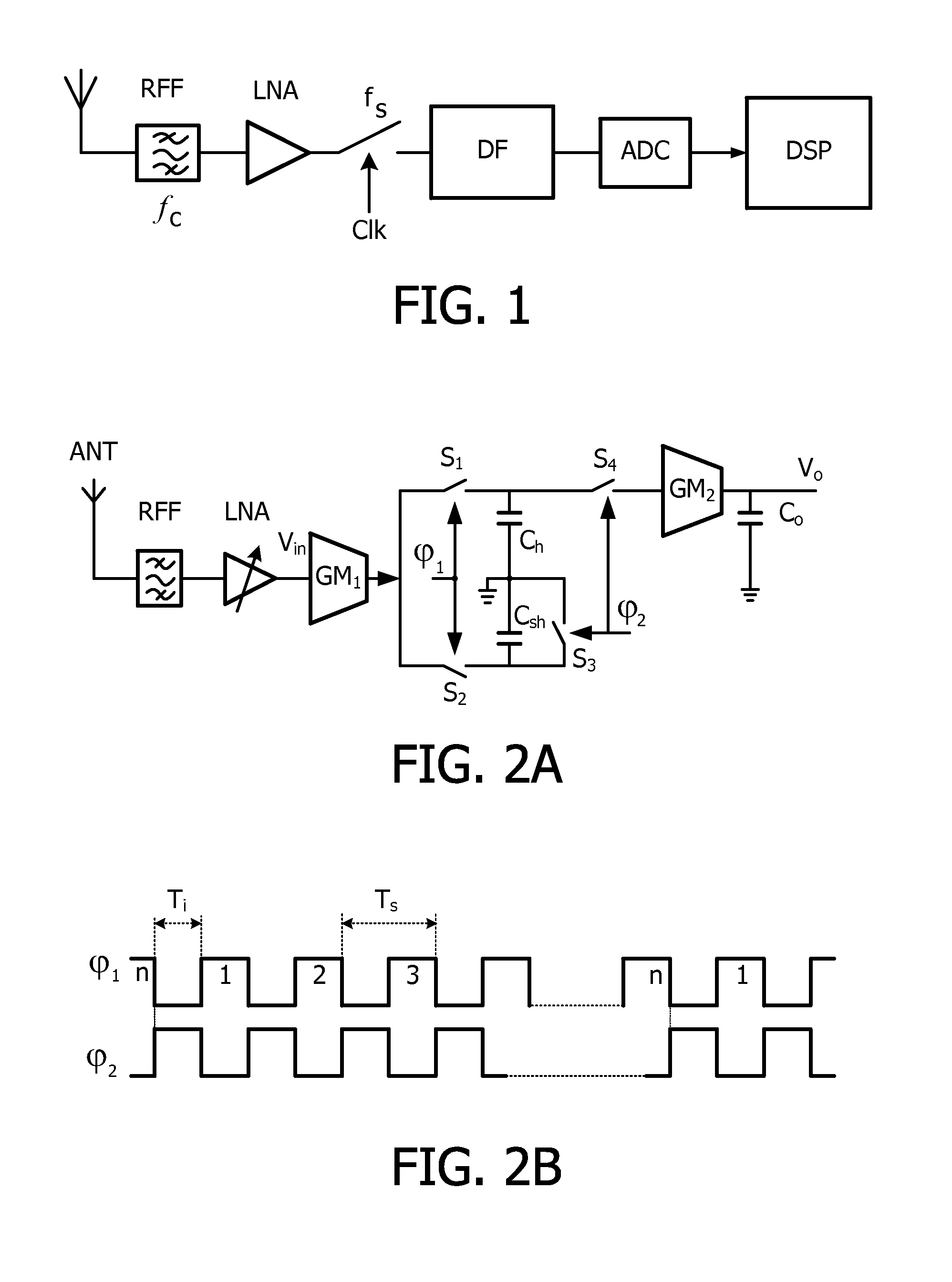
[0024]FIG. 2A shows a block diagram of an RF receiver comprising an RF sampling receiver according to an embodiment of the invention. The RF receiver comprises an antenna ANT, an RF filter RFF, a low noise amplifier LNA, a first transconductor unit Gm1, a first switch S1 and a second switch S2 under the control of a first clock signal φ1, a holding capacitor Ch, a sharing capacitor Csh, a third switch S3 and a fourth switch S4 under the control of a second clock signal φ2, a second transconductor unit Gm2, and an outputting capacitor Co.

[0025]The holding capacitor Ch and the sharing capacitor Cs, are coupled in parallel respectively by the first and second switches S1 and S2, and then coupled to the first transconductor unit Gm1 in series. The fourth switch S4 is connected between the holding capacitor Ch and the second transconductor unit Gm2. The third switch S3 is coupled with the sharing capacitor Csh in parallel. The output of the second transconductor unit Gm2 is coupled to th...


PUM


Abstract

The invention relates to an RF signal sampling apparatus for a wireless receiver, comprising a first transconductor circuit (Gmi), for converting received RF voltage signals into current signals, a first HR filter, for down-sampling and filtering the current signals, and an FIR filter, for further filtering, down-sampling and outputting the signals which are outputted by the first HR filter.

Description

FIELD OF THE INVENTION[0001]The invention relates generally to a wireless communication technology, and more particularly, to a radio frequency (RF) signal sampling apparatus and method for a wireless receiver.BACKGROUND OF THE INVENTION[0002]A conventional wireless receiver down-converts and fully filters the received RF signals in analog (continuous-time) domain. To reduce the cost of the receiver, the analog circuits and the digital signal processing (DSP) circuits usually should share the same semiconductor chip. Presently, the receiver architecture using RF sampling is highly desirable due to the fact that it is easy to reconfigure and integrate the analog and digital circuits on silicon chips of the same process. FIG. 1 is a block diagram showing usual architecture of an RF sampling receiver. The receiver comprises an antenna, an RF filter RFF, a low noise amplifier LNA, a switch under the control of a clock signal Clk, a discrete-time filter DF, an analog-to-digital converter...

Claims


Application Information

Patent Timeline
IPC IPC(8): H04B1/26
CPCH03D3/006H03H19/004H04B1/406H04B1/0007H04B1/0003
Inventor QIAN, XUECHENG
Owner QIAN XUECHENG
Features
  • Generate Ideas
  • Intellectual Property
  • Life Sciences
  • Materials
  • Tech Scout
  • Unparalleled Data Quality
  • Higher Quality Content
  • 60% Fewer Hallucinations
Learn More