Phase matching band-pass filter using exponential function approximation

a filter and exponential function technology, applied in the field of phase matching bandpass filter, can solve the problems of increasing the whole manufacturing cost of rf transceivers, and achieve the effects of high frequency selectivity, high q value and stability, and high performan

Inactive Publication Date: 2013-08-13
SAMSUNG ELECTRONICS CO LTD
View PDF4 Cites 0 Cited by
  • Summary
  • Abstract
  • Description
  • Claims
  • Application Information

AI Technical Summary

Benefits of technology

[0017]With the phase matching band-pass filter using the exponential function approximation according to the present invention, it is possible to implement a high performance phase matching band-pass filter with the conventional inductor and capacitor without using negative-R. By using the device of which impedance characteristic approximates to an exponential function in relation to frequency, it is possible to implement the filter having the high frequency selectivity as compared to the conventional filter and obtaining high Q value and stability as a channel selection filter.
[0018]With the phase matching band-pass filter using the exponential function approximation according to the present invention, it is possible to reduce the volume and manufacturing cost of the receiver significantly, by substituting the SAW filter, and reinforce the channel selection function, thereby mitigating the load of the digital front-end and analog-digital converter (ADC) of the digital circuit of the transceiver.

Problems solved by technology

However, the SAW filter which uses mechanical resonance is large in volume and impossible to integrate in the form of IC, resulting in increase of whole manufacturing cost of the RF transceiver.

Method used


Image

  • Phase matching band-pass filter using exponential function approximation
  • Phase matching band-pass filter using exponential function approximation
  • Phase matching band-pass filter using exponential function approximation

Examples


Embodiment Construction

[0027]Exemplary embodiments of the present invention are described hereinafter with reference to the accompanying drawings in detail. The same reference numbers are used throughout the drawings to refer to the same or like parts. Detailed description of well-known functions and structures incorporated herein may be omitted to avoid obscuring the subject matter of the present invention.

[0028]The terms and words used in this description and the appended claims are not to be interpreted in common or lexical meaning but, based on the principle that an inventor can adequately define the meanings of terms to best describe his / her own invention, to be interpreted in the meaning and concept conforming to the technical concept of the present invention.

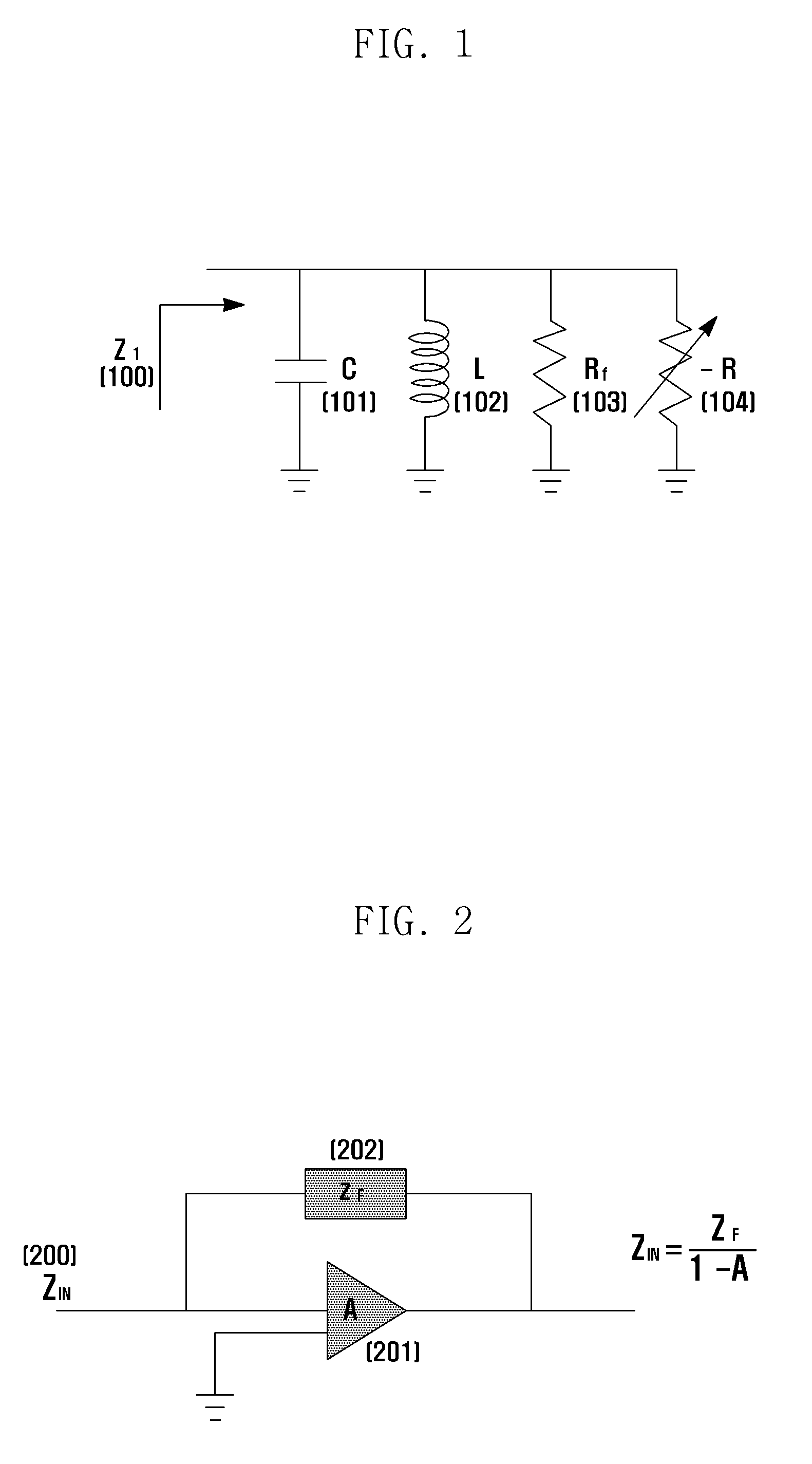
[0029]FIG. 1 is a circuit diagram illustrating a configuration of an inductor-capacitor filter device used in a general band-path filter.

[0030]Referring to FIG. 1, the typical band-pass filter uses the resonance characteristics of the capacitor...


PUM


Abstract

A The present invention relates to a phase matching band-pass filter using exponential function approximation, comprising an inductor including a parasitic resistor, a first device wherein a first amplifier is connected in a feedback mode, a capacitor including a parasitic resistor, a plurality of filter devices including a second device that is connected with a second amplifier in a feedback mode, and a coupling capacitor that connects the plurality of filter devices; the impedance of the first device has an increasing exponential function relation with a frequency, impedance of the second device has a decreasing exponential function relation with the frequency, and the first device is connected with the second device in parallel. According to the phase matching band-pass filter using exponential function approximation of this invention, conventional inductors and capacitors can be used 0 without modification or use of negative resistance, resulting in a high-performance phase matching band-pass filter. In addition, when a device with impedance characteristics that approximate an exponential function is used, the degree of frequency selection 0 becomes higher than that of conventional filters resulting in filters having high Q values and stability, such as channel selection filters.

Description

BACKGROUND OF THE INVENTION[0001]1. Field of the Invention[0002]The present invention relates to a phase matching band-pass filter and, in particular, to a phase matching band-pass filter composed of devices having impedance changes following an exponential function in relation to frequency.[0003]2. Description of the Related Art[0004]The transceiver for use in baseband communication is provided with a low-pass filter to filter out the interferer while passing the original signal. Most communications are done over radio frequency carriers to avoid interference from each other, and the Radio Frequency (RF) transceiver of an RF system should use an RF band-pass filter that pass signals from a specific frequency band on which it operates.[0005]In the current frequency allocation system in which the entire range of frequency spectrum is densely allocated for different usages, the load of the digital front end or converter (ADC) of the transceiver increases due to the other frequency ban...

Claims


Application Information

Patent Timeline
Patent Type & Authority Patents(United States)
IPC IPC(8): H03K5/00
CPCH03H7/0115H03H11/48
Inventor PARK, HAN GUEYOON, BYUNG TAELEE, JAE SUBSON, MI HYUNZEONG, JONG WOOK
Owner SAMSUNG ELECTRONICS CO LTD
Why Eureka
Try Eureka