
Puncture device and method for controlling same

a technology of a device and a control device, applied in the field of puncture, can solve the problems of increased pain to patients, increased risk of infection, and increased risk of infection, and achieve the effects of improving energy efficiency, reducing voltage, and high energy efficiency

Inactive Publication Date: 2010-04-29
PANASONIC CORP
View PDF8 Cites 44 Cited by
  • Summary
  • Abstract
  • Description
  • Claims
  • Application Information

AI Technical Summary

Benefits of technology

[0019]It is an object of the present invention to solve this problem, and to provide a puncture device with improved energy efficiency.
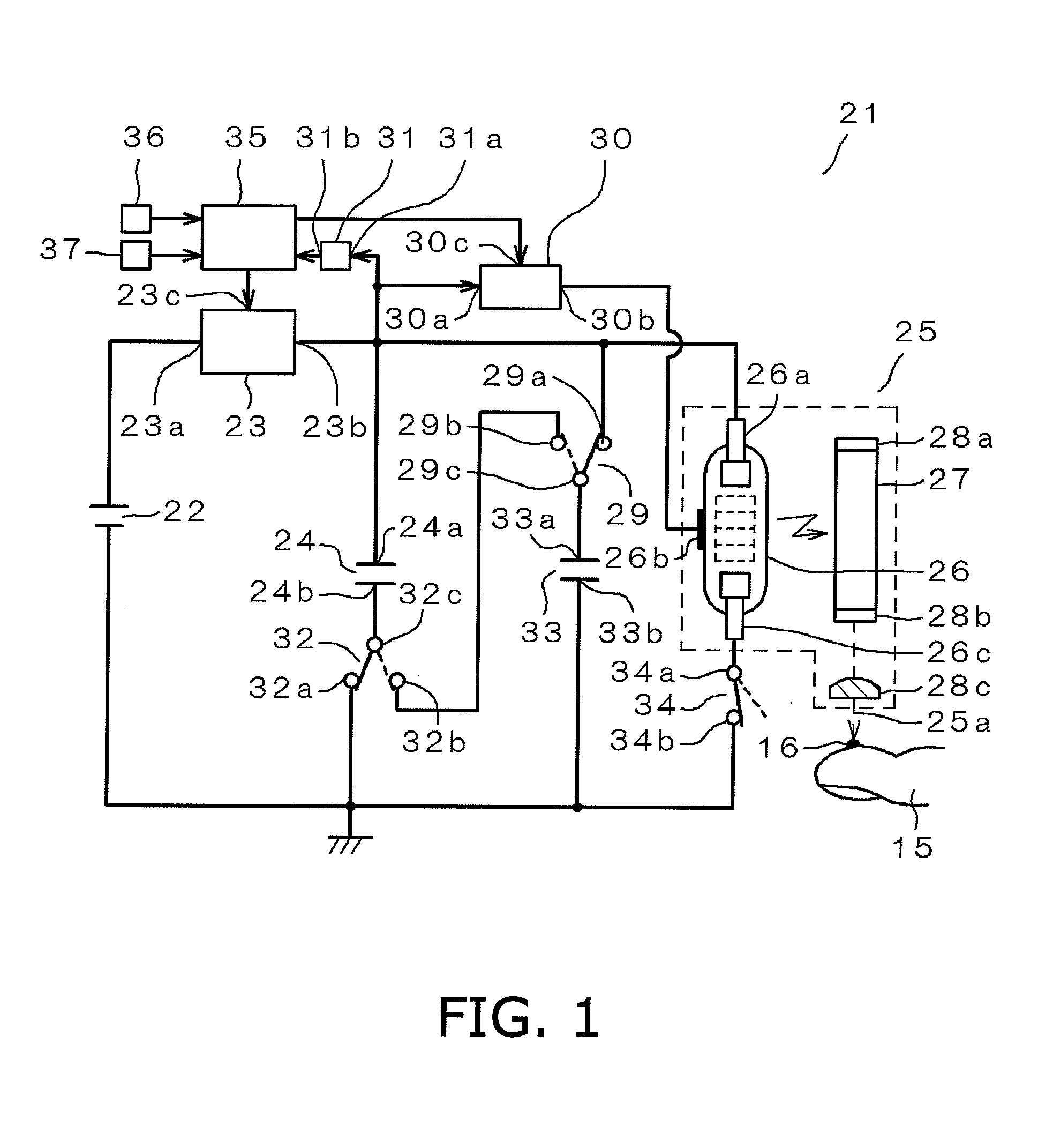
[0020]To achieve this object, the puncture device of the present invention comprises a plurality of capacitors and a switching circuit that switches the connection of these capacitors. The controller also controls the switching circuit so as to carry out a first puncture, which is performed with the capacitors connected in parallel, and a second puncture, which is performed with the capacitors connected in series at the same place as the first puncture. This allows the above-mentioned object to be achieved.
[0021]Specifically, the first puncture lowers the voltage with which the plurality of capacitors connected in parallel are charged. However, even though it drops to the level at which the emission of laser light stops, a voltage level at which the emission of the laser beam is possible can be ensured by connecting these capacitors in series. The second puncture can be performed in series at the same place as the first puncture. That is, a puncture can be performed and blood collected at a high energy efficiency, without wasting the energy with which the capacitors are charged.
[0022]Also, when a puncture is made with a laser, ablation occurs so that the puncture diameter becomes greater proportional to the puncture depth. Accordingly, since a puncture depth that goes all the way down to the dermis layer is obtained all at once, the puncture diameter inevitably increases, which causes more pain to the patient. Furthermore, since the irradiation time increases in a single irradiation, the heat of the laser may cause the tissue to coagulate, producing a hemostatic effect. Therefore, the patient has to make a larger hole in the skin surface, and this may further aggravate the patient's pain.
[0023]In contrast, when two or more punctures are made as in the present invention, the puncture diameter can be reduced by making a plurality of punctures at a shallower depth. Furthermore, since a single laser irradiation takes less time, the tissue of the skin surface is not affected by heat, and blood can be obtained with a smaller hole, so less pain is inflicted on the patient.

Problems solved by technology

Nevertheless, because these products involve contact, there is the risk of infection.
Although the laser beam 6f is not outputted, the flash lamp 6a remains on, so energy efficiency suffers, which can be a particularly serious problem in portable devices that are battery driven.
Accordingly, since a puncture depth that goes all the way down to the dermis layer is obtained all at once, the puncture diameter inevitably increases, which causes more pain to the patient.
Furthermore, since the irradiation time increases in a single irradiation, the heat of the laser may cause the tissue to coagulate, producing a hemostatic effect.
Therefore, the patient has to make a larger hole in the skin surface, and this may further aggravate the patient's pain.

Method used


Image

  • Puncture device and method for controlling same
  • Puncture device and method for controlling same
  • Puncture device and method for controlling same

Examples


embodiment 1

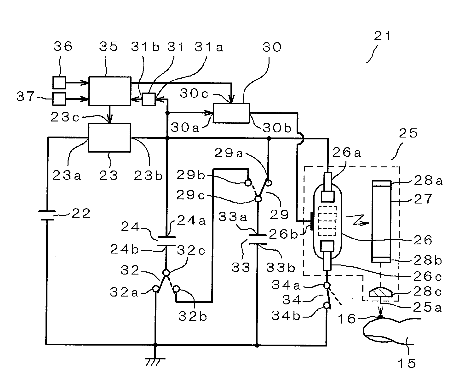
[0039]An embodiment of the present invention will now be described through reference to the drawings. FIG. 1 is a block diagram of a puncture device 21 in Embodiment 1. In FIG. 1, 22 is a lithium ion battery (an example of a power supply) that outputs a voltage of 3.7 V.

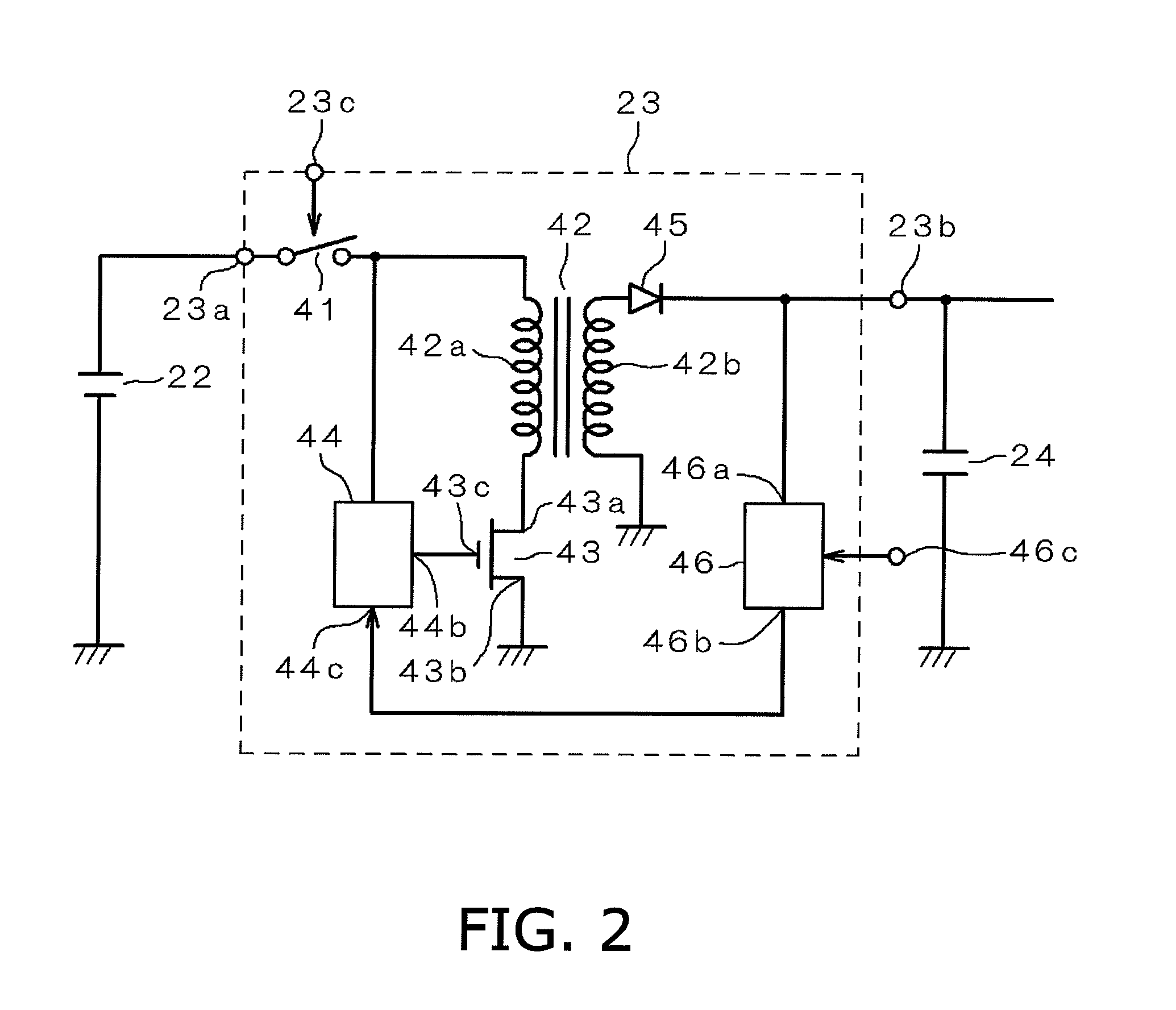
[0040]The negative side of the battery 22 is connected to ground, while the positive side is connected to an input 23a of a booster circuit 23. Either a primary cell or a secondary cell can be used as the battery 22. The means for supplying power to the puncture device 21 is not limited to the battery 22, and some other power supply means may be employed instead. The booster circuit 23 does not necessarily have to be provided to the puncture device 21.

[0041]The output 23b of the booster circuit 23 is connected to the positive side 24a of a capacitor 24 having an electrostatic capacity of 300 μf, the anode 26a of a flash lamp 26 (an example of a light source), one of the selection terminals 29a of a switch 29 formed f...

embodiment 2

[0077]A blood testing device 101 will be described in this embodiment, in which the laser puncture device 21 described in Embodiment 1 above is used. The components having the same function as in Embodiment 1 above will be numbered the same and not described again.

[0078]FIG. 6 is a cross section of the blood testing device 101 in this embodiment. In FIG. 6, 102 is a housing with a cuboid shape, and is molded from plastic.

[0079]This housing 102 has a main body 102a and a cover 102b rotatably provided to the main body 102a via a fulcrum 102c. Whether the cover 102b is open or closed is detected by an opening sensor 102f mounted on the lower side 102d of the main body 102a. The cover 102b can be latched at a first opening angle of approximately 30 degrees or a second opening angle of approximately 90 degrees.

[0080]A puncture component 104 in which blood sensors (hereinafter referred to as “sensors”) 123 are inserted and supported is provided to the corner of the lower side 102d of the ...


PUM


Abstract

A puncture device 21 comprises capacitors 24 and 33 to which voltage is applied, a laser puncture unit 25 to which the output of these capacitors 24 and 33 is supplied, a trigger circuit 30 that applies a trigger voltage to the laser puncture unit 25, and a controller 35 that controls this trigger circuit 30. The puncture device 21 further comprises switches 29 and 32 that switch the connection of the capacitors 24 and 33. The switches 29 and 32 are controlled by the controller 35 so as to carry out a first puncture, which is performed with the capacitors 24 and 33 connected in parallel, and a second puncture, which is performed with the capacitors 24 and 33 connected in series.

Description

CROSS-REFERENCE TO RELATED APPLICATIONS[0001]This application claims priority to Japanese Patent Application No. 2008-277967. The entire disclosure of Japanese Patent Application No. 2008-277967 is hereby incorporated herein by reference.BACKGROUND[0002]1. Technical Field[0003]The present invention relates to a puncture device that makes use of a laser, and to a method for controlling this device.[0004]2. Description of the Prior Art[0005]Many puncture methods that involve the use of a needle are currently being used as methods for collecting tiny amounts of blood from the skin, and many needle-type puncture devices are on the market. Nevertheless, because these products involve contact, there is the risk of infection. Accordingly, laser puncture devices have been developed which allow non-contact puncture to be performed.[0006]A conventional laser puncture device will now be described. FIG. 13 is a block diagram of a conventional puncture device.[0007]As shown in FIG. 13, a convent...

Claims


Application Information

Patent Timeline
Patent Type & Authority Applications(United States)
IPC IPC(8): A61B18/20
CPCA61B5/1411A61B2017/00734A61B18/20A61B5/150022A61B5/150099A61B5/150175A61B5/150358A61B5/15113A61B5/15136A61B5/157
Inventor MATSUMURA, KEISUKEHORIKAWA, KIYOHIRO
Owner PANASONIC CORP
Learn More