
LED luminaire with automatic luminance compensation

Inactive Publication Date: 2010-05-06
MATSUSHITA ELECTRIC WORKS LTD
View PDF3 Cites 4 Cited by
  • Summary
  • Abstract
  • Description
  • Claims
  • Application Information

AI Technical Summary

Benefits of technology

[0019]In view of the foregoing, it is an object of the present invention to reduce degradation of luminous flux from a luminaire or lamp fixture caused by luminous flux deterioration in an LED package having an LED chip and a reflector section made of silver that reflects light from the LED chip.
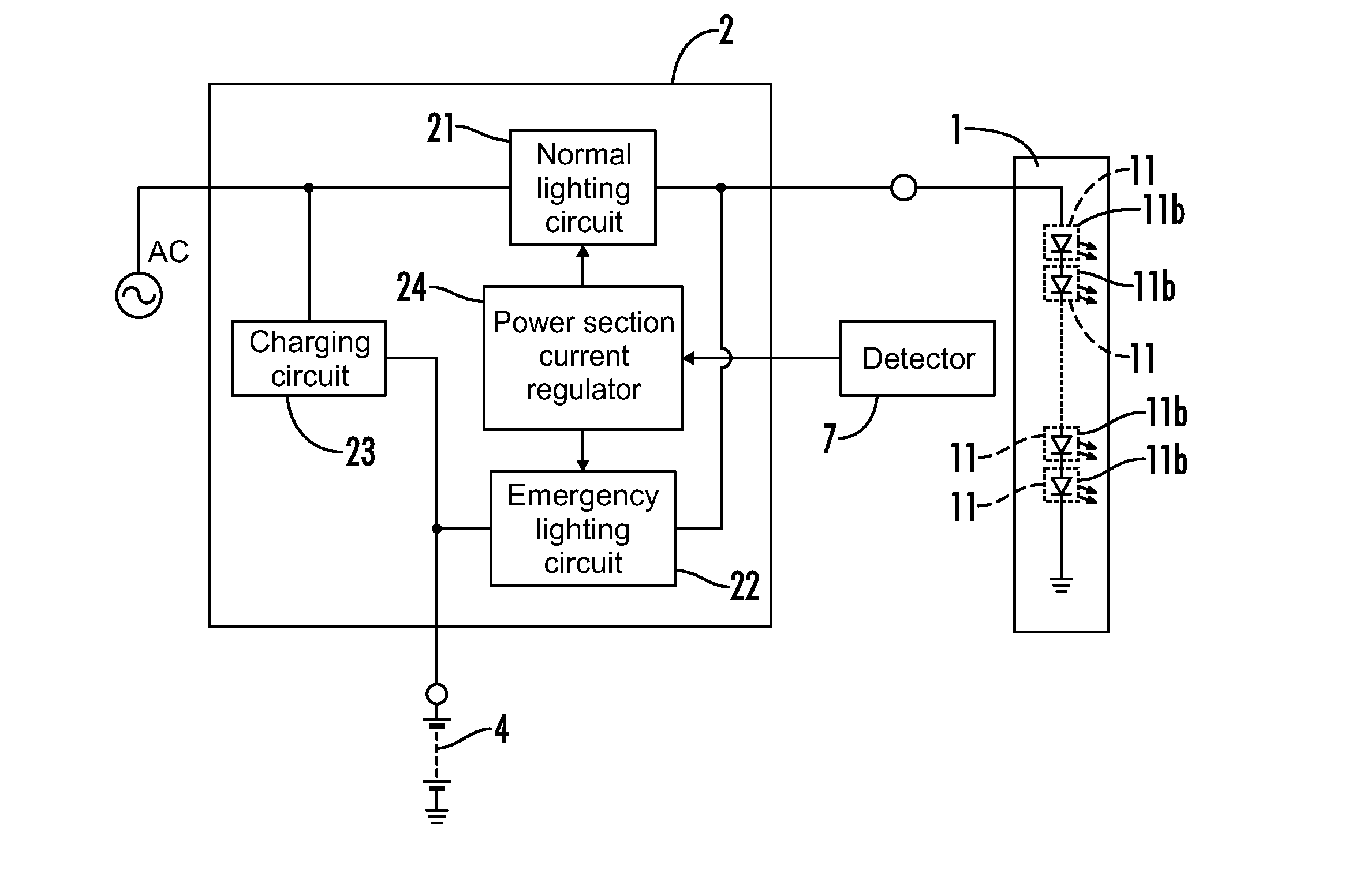
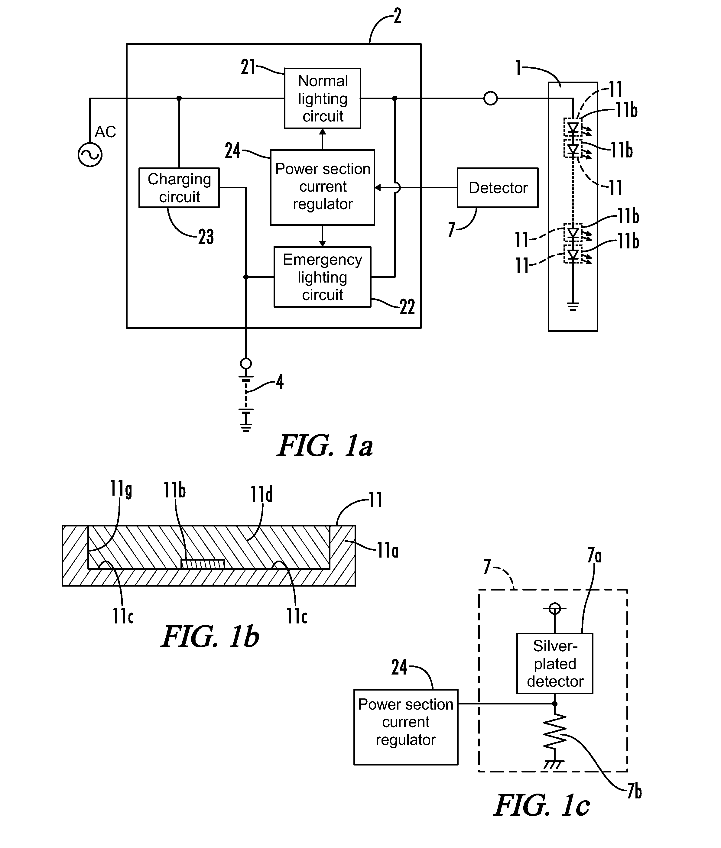
[0021]According to the present invention, the power section upwardly adjusts the power supplied to the lamp section increase when an increase in the resistance value is detected at the silver-plated detector in the detection section, thereby compensating the luminous flux deterioration of the lamp. Therefore, it is possible to minimize a decrease in luminous flux emitted from the luminaire due to the luminous flux deterioration of the lamp generated when the reflector section reacts with sulfur, causing the inside of the lamp to sulfurize and blacken.
[0023]According to an embodiment of the present invention, the silver-plated detector placed within the lamp reduces a difference in sulfidity between the silver-plated detector and the surface of the reflector section, thereby enabling more accurate compensation of luminance flux. Further, no attachment member is required for attaching the silver-plated detector to the luminaire, so that the cost can be reduced by reduction in component count. It is also possible to avoid the labor cost of attaching the silver-plated detector to the luminaire.
[0025]According to one aspect of the present invention, the silver-plated detector has a reflection function for reflecting the light from the LED chip, which can improve efficiency and enabling energy savings.
[0027]According to another aspect of the present invention, the power section current regulator may adjust the magnitude of the current applied to the power section corresponding to the resistance value of the silver-plated detector, further according to normal conditions times in which the normal lighting circuit powers the power section, and in an emergency in which the emergency lighting circuit powers the power section. In this way, the luminaire can be used with a different standard for average brightness of the entire display surface in both normal conditions and in an emergency.
[0028]According to the first aspect of the present invention, the luminous flux deterioration of the lamp is compensated by causing the power supplied from the power section to increase when the raise in the resistance value is detected at the silver-plated detector.

Problems solved by technology

Therefore, the wires connecting the ballast to the cold cathode lamp decrease the power supplied to the cold cathode lamp because of the influence of a stray capacitances.
This may decreases the light output of the cold cathode lamp, so that some efforts are necessary to make the wiring as short as possible.
The cold cathode lamp thus cannot be lit even at the time of disaster such as a power outage.
In the case where the luminaire is operated by means of, for example, a remote control device so as to check circuit operation of the luminaire, the remote control may malfunction because of noise generated from the cold cathode lamp.
Moreover, since the amount of free sulfur varies depending on the usage of the luminaire, it is difficult to predict when the surface of the reflector section of the lamp will be blackened.
In the prior art luminaires that use an LED light source, approximately 30% of luminous flux deterioration occurs due to the degradation of the translucent resin at lamp end of life.
However, again referring to FIG. 7, there is a reliability problem when prior art luminaires 11″ use a protection film 11f″ made of silicon nitride and the like on a surface 11c″ of the LED reflector section.

Method used


Image

  • LED luminaire with automatic luminance compensation
  • LED luminaire with automatic luminance compensation
  • LED luminaire with automatic luminance compensation

Examples


Embodiment Construction

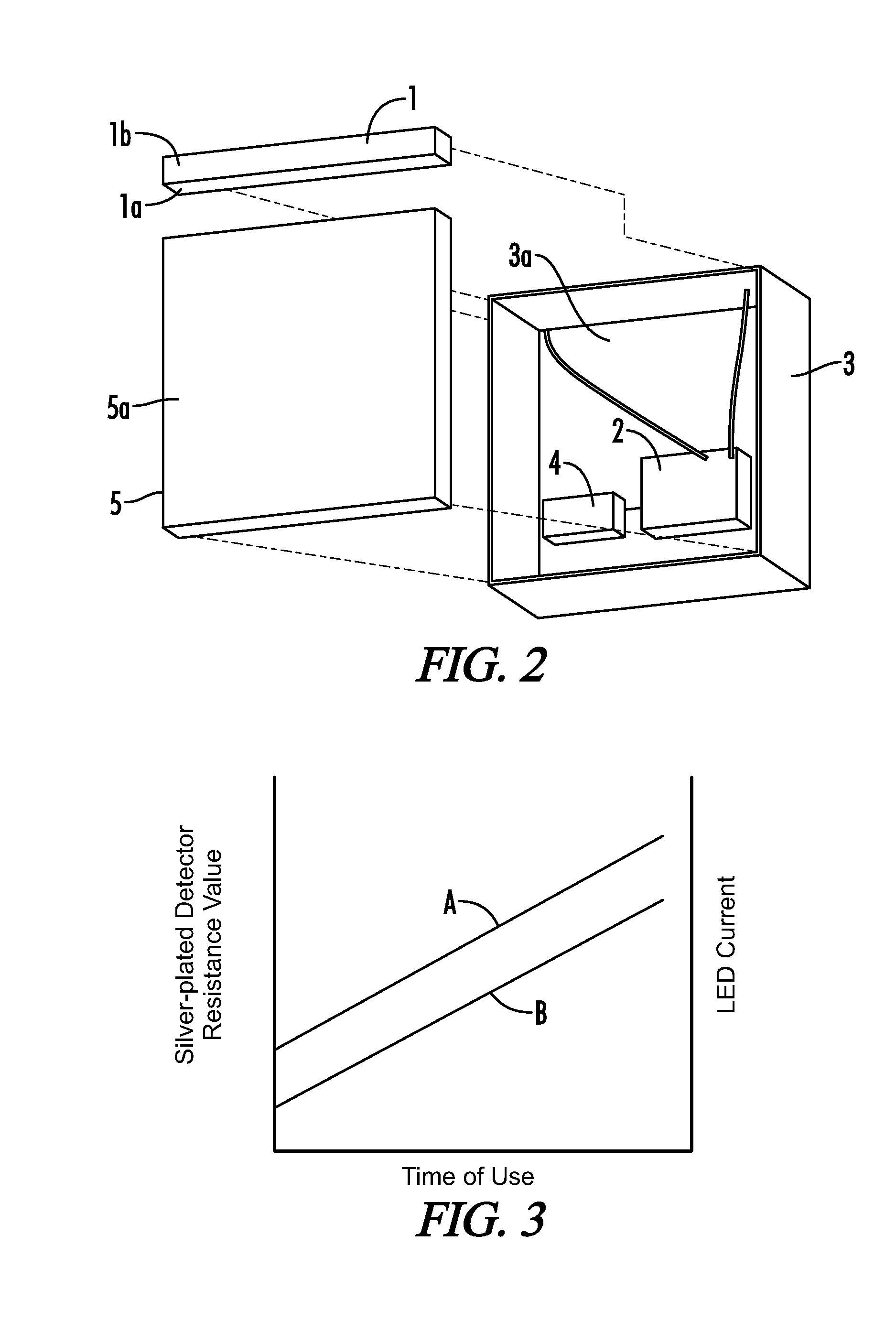
[0039]Referring to FIGS. 1a and 2, one embodiment of the luminaire of the present invention is an emergency guide light provided with a lamp section 1 including a plurality of lamps 11, a power section 2 which receives power supplied from a commercial power source AC to power the lamp section 1, and a fixture main body 3 accommodating the power section 2 therein. The fixture main body 3 also accommodates a back-up battery section 4 capable of powering the power section 2 when the power supplied from the commercial power source AC to the power section 2 is shut off due to, for example, a power outage.

[0040]As shown in FIG. 2, the fixture main body 3 is formed into a rectangular box shape having an opening 3a on a front side. The fixture main body 3 also includes a display panel 5 arranged on a front side thereof which covers a part of the opening 3a as well as allows light emitted from the lamp section 1 to exit from a display surface 5a. Furthermore, the luminaire of the present emb...


PUM


Abstract

An LED luminaire for normal or emergency lighting has a lamp section comprising a least one LED lamp, the LED lamp having an LED chip and a reflector section. The reflector section is formed of silver and is positioned to reflect light from the LED chip. A power section is coupled to supply power to the lamp section. A detector section has a silver-plated detector and is functional to detect sulfuration of the reflector section as a resistance value change. The power section is operable to adjust the power supplied to the lamp section upon detecting an increase in the resistance value at the silver-plated detector of the detector section.

Description

[0001]A portion of the disclosure of this patent document contains material that is subject to copyright protection. The copyright owner has no objection to the reproduction of the patent document or the patent disclosure, as it appears in the U.S. Patent and Trademark Office patent file or records, but otherwise reserves all copyright rights whatsoever.CROSS-REFERENCES TO RELATED APPLICATIONS[0002]This application claims benefit of the following patent application(s) which is / are hereby incorporated by reference: Japanese Patent Application No. 2008-217428, filed Aug. 26, 2008.STATEMENT REGARDING FEDERALLY SPONSORED RESEARCH OR DEVELOPMENT[0003]Not ApplicableREFERENCE TO SEQUENCE LISTING OR COMPUTER PROGRAM LISTING APPENDIX[0004]Not ApplicableBACKGROUND OF THE INVENTION[0005]The present invention relates generally to luminaires. More particularly, the present invention pertains to LED luminaires used as a source of normal and emergency lighting.[0006]There are conventional luminair...

Claims


Application Information

Patent Timeline
IPC IPC(8): H02J9/00H05B37/02
CPCF21S9/022H05B33/0803H05B33/0872H02J9/065Y10T307/625H05B45/20H05B45/00H05B45/395
Inventor TACHINO, YOUJIYAMASHITA, KOJI
Owner MATSUSHITA ELECTRIC WORKS LTD
Learn More