AC to DC LED illumination devices, systems and methods

a technology of led lamps and drive circuits, applied in the direction of electric variable regulation, process and machine control, instruments, etc., can solve the problems of high replacement cost versus other lamp technologies, not very competitive to use expensive drive circuitry to operate led lamps off the mains, and cannot be said the same for led lamps operated directly from the mains power supply

Active Publication Date: 2010-05-06
GT BIOMESCILT LIGHT
View PDF17 Cites 91 Cited by
  • Summary
  • Abstract
  • Description
  • Claims
  • Application Information

AI Technical Summary

Problems solved by technology

Whereas LED applications in the non-illumination sectors have many well established designs for drive circuitry, the same cannot be said for LEDs operated directly from the mains power supply.
As such, it is not very competitive to use expensive drive circuitry to operate LED lamps off the mains because the replacement cost versus other lamp technologies will be higher and the payback time will be longer.
For LEDs to be operated from the mains directly, the first challenge is the cost of the AC to DC power adapter.
However, these schemes introduce the problems of lower power factor and high total harmonic distortion to the power supply.
While the constant DC current provides efficient LED operation, the drive circuit and power adapter have a high component count and consequently a high cost is involved.
In addition, a large amount of space is taken up by this design due to the size and number of components used.
This is rather undesirable when the power adapter and drive circuit have to be fitted into the size of a conventional light bulb.
However, one limitation of this design is that the voltage and current follow half-sinusoidal waveforms, which are not suitable for driving LEDs.
Half-wave rectification is not competitive due to low light output as a result of missing half a cycle of operation in DC mode.
This is partly due to the high turn-on voltage of the LED and this results in lower flux output for a full wave rectification-based LED module.
The waveform of the current and voltage generated by the full wave rectification circuit is not optimal in light output efficiency in terms of lumens per watt of the system.
Full wave rectification without modification of the sinusoidal forward voltage and forward current waveforms would severely limit the drive current through the LEDs throughout much of the power cycle, resulting in a rather low overall average DC current and low average power. FIG. 2 shows an example of the luminous intensity (lv) waveform resulting from a full wave rectified power supply.
However, the capacitive load causes harmonic distortion to the power supply and there is a drop in the power factor of the system.
The main losses of the system include power loss in resistor R2 of the AC-to-DC conversion block and power loss in resistor R1 used to limit the current flowing through the LEDs.
The complex circuit has a higher component count and increases the cost of the design to supply DC power to an LED string.
For a low cost product such as an LED lamp, these schemes are not suitable although the DC power supply quality is good in terms of high power factor and low harmonic distortion to the power supply.
Another problem with driving LEDs directly off the AC mains is the variation in forward voltage of individual LEDs due to their mass production.
This increases the manufacturing cost of LEDs to cover the cost of rejects in the forward voltage binning process.
These components introduce electromagnetic radiation noise and as a result require additional EMI suppression measures in the circuit design.
In addition, the magnetic coils cause humming noise in the presence of magnetic parts, for example, in fluorescent tube lighting fixtures.
However, these designs suffer from one or more of the aforementioned problems or drawbacks.
Drawbacks are also encountered with conventional systems for controlling colored LEDs being powered from an AC supply.
Pulse width modulation has the advantage of high efficiency in lumens per watt, but a drawback is the need for complex circuitry to implement the color mixing, including the use of LED drivers, color control integrated circuits (ICs), a microprocessor and a power adapter for low voltage supply.
Although this method is cheaper and simpler than pulsed width modulation, it reduces the efficiency of the illumination system through heat losses in the series resistance, especially at high dimming levels.

Method used


Image

  • AC to DC LED illumination devices, systems and methods
  • AC to DC LED illumination devices, systems and methods
  • AC to DC LED illumination devices, systems and methods

Examples


Embodiment Construction

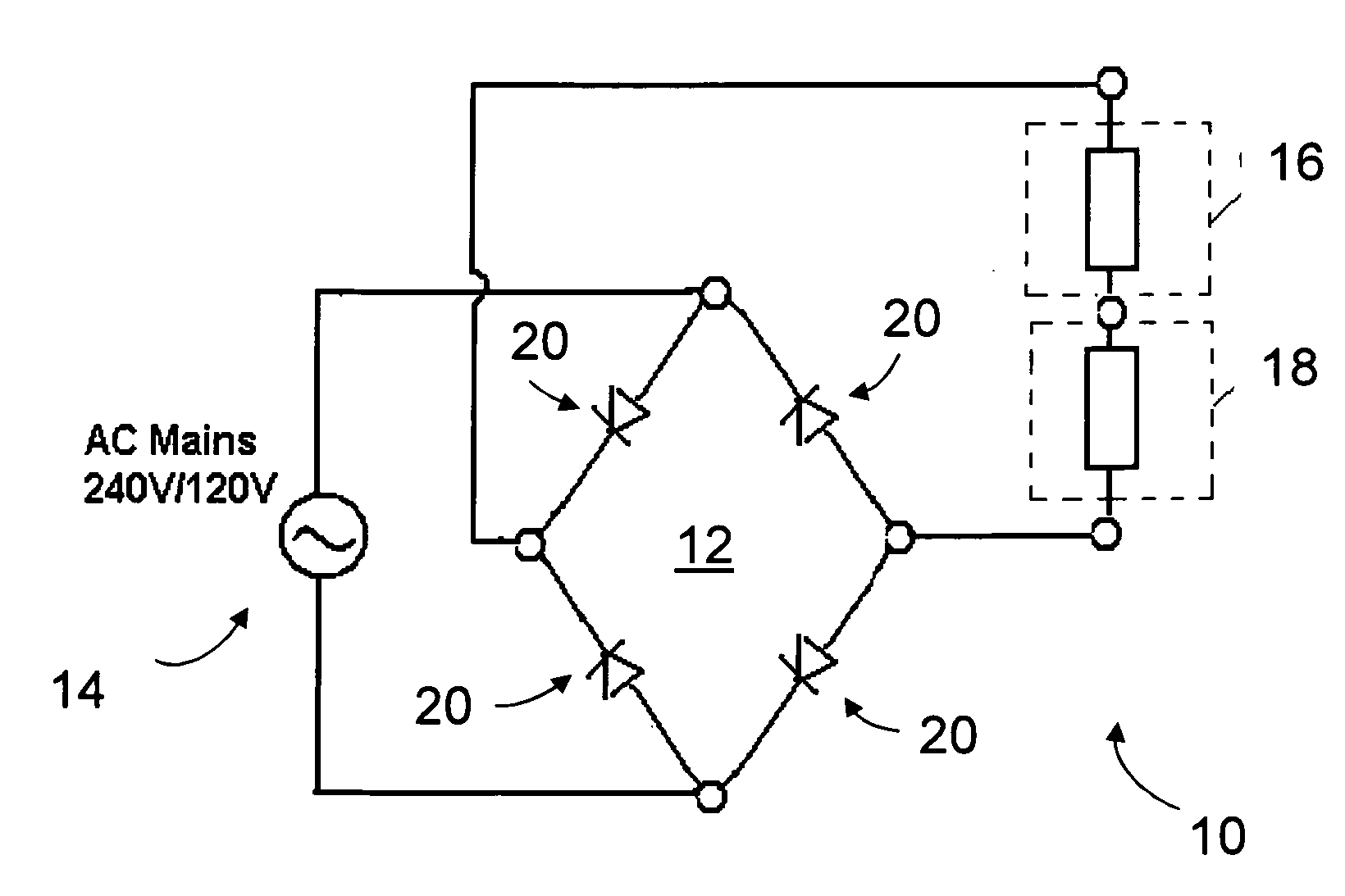
[0091]Referring to FIG. 4, an illumination device 10 provided in accordance with embodiments of the present invention comprises a rectifier 12 coupled to an alternating current (AC) supply 14 for converting the AC supply 14 into a direct current (DC). A current limiting diode (CLD) module 16 is coupled in series to an output of the rectifier 12 and a light emitting diode (LED) module 18 is coupled in series between an output of the CLD module 16 and the rectifier 12.

[0092]The LED module 18 can comprise one or more LEDs in series and / or two or more LEDs in parallel. According to some embodiments, the LED module 18 can comprise one or more LED blocks, with each LED block comprising two or more LEDs in parallel and / or in series. The CLD module 16 can comprise a single CLD or two or more CLDs in parallel. The arrangements of the LEDs and the CLDs will be described in further detail hereinafter. It will be appreciated by the skilled addressee that the term “LED module” includes a single ...


PUM


Abstract

Illumination devices (10), systems and methods that convert an alternating current (AC) supply (14) to a direct current (DC) for powering a plurality of light emitting diodes (LEDs) are disclosed. An illumination device (10) comprises a full wave rectifier (12) for converting the AC supply into a direct current (DC). A current limiting diode (CLD) module (16), comprising at least two CLDs coupled in parallel, is coupled in series to an output of the full wave rectifier and a light emitting diode (LED) module (18) comprising a plurality of LEDs is coupled in series between an output of the CLD module (16) and the full wave rectifier (12).

Description

FIELD OF THE INVENTION[0001]Embodiments of the present invention relate generally to illumination devices, systems and methods that convert an alternating current (AC) to a direct current (DC) for powering one or more light emitting diodes (LEDs).BACKGROUND TO THE INVENTION[0002]The rapid development in LED efficiency in recent years has resulted in the adoption of LEDs in illumination applications, replacing incandescent bulbs in many applications and beginning to replace cold cathode fluorescent lamps (CCFLs) and fluorescent tube lamps in some specialty lighting applications. Whereas LED applications in the non-illumination sectors have many well established designs for drive circuitry, the same cannot be said for LEDs operated directly from the mains power supply. Unlike other applications, LED lamp products used for illumination have to compete against incandescent lamps and CCFLs with low entry cost. As such, it is not very competitive to use expensive drive circuitry to operat...

Claims


Application Information

Patent Timeline
Patent Type & Authority Applications(United States)
IPC IPC(8): H05B37/02H05B44/00
CPCH05B33/0803H05B33/0809H05B33/0821Y02B20/342H05B45/40H05B45/37Y02B20/30H05B45/345
Inventor CHEW, TONG FATT
Owner GT BIOMESCILT LIGHT
Why Eureka
Try Eureka