Power factor correction power supply unit, and control circuit and control method used in the same

a power factor correction and power supply unit technology, applied in the field of pfc (power factor correction) power supply units, can solve the problems of complex configuration of inductors, easy malfunction, and difficulty in reducing the cost of pfc converters and reducing the profile, so as to prevent continuous operation, prevent malfunction, and simplify the effect of inductors

Active Publication Date: 2010-05-06
FUJI ELECTRIC CO LTD
View PDF7 Cites 36 Cited by
  • Summary
  • Abstract
  • Description
  • Claims
  • Application Information

AI Technical Summary

Benefits of technology

[0033]According to the invention, it is possible to realize a critical PFC converter requiring no auxiliary winding as in a drain voltage detection system. It is therefore possible to simplify an inductor, and it is unnecessary to consider the trouble caused by short-circuiting of the auxiliary winding. Further, there are no defects inherent to a minus current detection system. It is therefore possible to obtain effects to prevent continuous operation, to prevent malfunction due to noise, to improve power efficiency, and so on. Further, it is also possible to design critical interleave requiring no auxiliary winding.
[0034]In addition, according to the invention, an ON delay is inserted so that it is possible to prevent from disturbing zero-current switching due to accumulated computing errors.

Problems solved by technology

Therefore, the configuration of the inductors L1, L2 is complicated.
Further, short-circuit protection for the auxiliary winding L2 is also required to make it difficult to lower the cost of the PFC converter and reduce the profile thereof.
(2) Due to a low minus current detection level, the converter is so sensitive to noise from a current loop so that malfunction occurs easily.
(3) Power consumption increases due to the minus current detection resistor.
(4) It is difficult to establish a critical interleave.
When the input voltage Vi is higher than a half of an output voltage Vo in this case, the delay time becomes insufficient.
When the input voltage Vi is higher than the half of the output voltage Vo, the delay time becomes insufficient.
Therefore, the critical point cannot be detected by the current detection resistor R.

Method used


Image

  • Power factor correction power supply unit, and control circuit and control method used in the same
  • Power factor correction power supply unit, and control circuit and control method used in the same
  • Power factor correction power supply unit, and control circuit and control method used in the same

Examples


Embodiment Construction

[0052]Embodiments of the invention will be described below in detail.

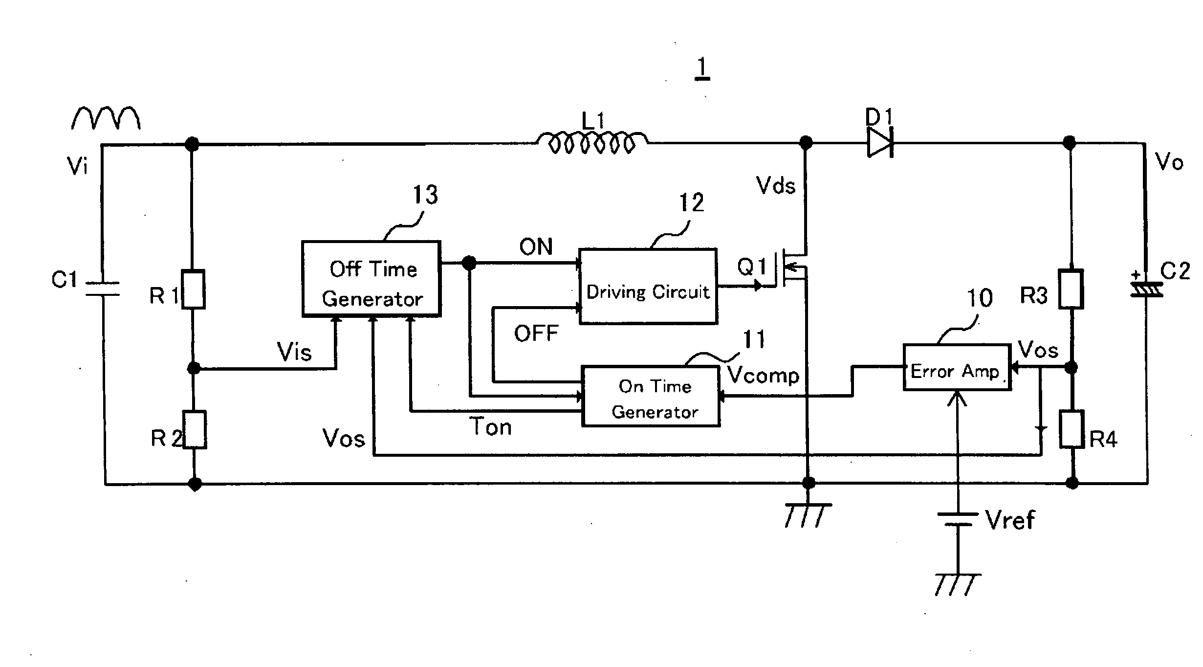
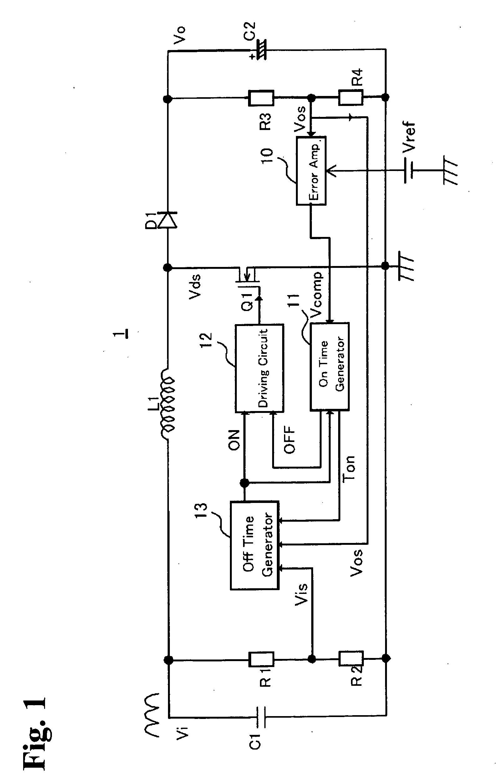
[0053]A fundamental concept of a critical PFC converter according to the invention is to perform predetermined arithmetic operations upon a value of an ON width of a switching device, a value of an input voltage and a value of an output voltage, respectively, to determine a critical point of the critical PFC converter, that is, a turn-on timing of the switching device. The fundamental concept will be described below further in detail.

[0054]Consider the aforementioned background-art critical PFC converter. The frequency of the input voltage Vi and the ripple frequency of the output voltage Vo are not more than 50 Hz to 60 Hz and 100 Hz to 120 Hz respectively. A switching frequency of approximately 100 kHz is often used. Based on this point, the switching frequency is about 1,000 times as high as the ripple frequency of the input voltage Vi and the output voltage Vo. Accordingly, the input voltage Vi and the output v...


PUM


Abstract

A power factor correction power supply unit for correcting a power factor includes a switching device, an input voltage detection circuit, an output voltage detection circuit, an error amplifier for outputting an error signal obtained by amplifying a difference between an output voltage detection signal and a reference voltage, an ON width generation circuit for generating an ON time width, an OFF width generation circuit for generating an OFF time width of the switching device, and a switching device driving circuit. The drive circuit conducts an ON/OFF control over the switching device upon receiving a turn-on timing signal for turning on the switching device as soon as the OFF time width is terminated and upon receiving a turn-off timing signal for turning off the switching device as soon as the ON time width is terminated.

Description

BACKGROUND OF THE INVENTION AND RELATED ART STATEMENT[0001]The present invention relates to a PFC (Power Factor Correction) power supply unit, and a control circuit and a control method used in the same. The present invention particularly relates to a switching power supply unit which converts an AC input from an AC power supply into a DC output with a high power factor.[0002]As known well, AC power includes active power, reactive power and apparent power. Only power which can be converted in AC / DC conversion is the active power. Therefore, it can convert more power into DC as the power factor is higher (closer to 100%). For this reason, PFC (Power Factor Correction) is normally conducted when designing a switching power supply unit.[0003]FIG. 11 is a diagram showing the configuration of a typical PFC converter. FIG. 11 shows the configuration of a PFC boost converter which controls a stable output voltage while creating an input current proportional to an input voltage by means of ...

Claims


Application Information

Patent Timeline
Patent Type & Authority Applications(United States)
IPC IPC(8): G05F1/00
CPCH02M1/4225Y02B70/126Y02P80/112Y02B70/10Y02P80/10
Inventor CHEN, JIAN
Owner FUJI ELECTRIC CO LTD
Why Eureka
Try Eureka