Laser light source, and image display apparatus and processing apparatus using the same

a technology of image display apparatus and laser light source, which is applied in the direction of instruments, optical elements, optics, etc., can solve the problems of inability to efficiently perform wavelength conversion, inability to stabilize wavelength conversion, and difficulty in continuous oscillation of semiconductor laser in room temperature, so as to achieve stable output and reduce output variation. , the effect of reducing the variation of the conventional temperature constant control

Inactive Publication Date: 2010-05-06
PANASONIC CORP
View PDF10 Cites 9 Cited by
  • Summary
  • Abstract
  • Description
  • Claims
  • Application Information

AI Technical Summary

Benefits of technology

[0018]In the laser light source, the multiple optical paths along which the excitation light passes are formed in the wavelength converting element, and the temperature of the wavelength converting element is controlled by monitoring the reference light having the temperature characteristic different from the temperature characteristic of the output light serving as the wavelength converted light to be outputted to the exterior of the laser light source. Accordingly, high-speed temperature control can be performed. As a result, output variation which has occurred in the conventional temperature constant control can be remarkably reduced, and output can be stabilized.

Problems solved by technology

A semiconductor laser for generating light of a wavelength in a mid infrared region of 2 μm or more is required to be cooled in a temperature zone from −100° C. to −200° C., and continuous oscillation of the semiconductor laser in a room temperature is difficult.
As a result, wavelength conversion cannot be performed efficiently.
Accordingly, in any case, stable wavelength conversion cannot be performed, unless the temperature of the wavelength converting element is stabilized.
In this control, however, an increase in electric power consumption cannot be avoided.
Also, since the output of excitation light has a limit, the allowable temperature difference is limited.
Furthermore, since the beam quality of wavelength converted light to be outputted in a condition that the element temperature and the phase matching temperature are different is poor, it is difficult to apply the light source to a processing apparatus or a medical apparatus requiring a high-quality laser output.
In the case where a wavelength converting element is disposed in a consumer device such as a backlight device of a projection display device or a liquid crystal display device, since the temperature in the casing is gradually increased, a difference between the element temperature and the phase matching temperature may frequently occur, and the output may be unstable each time the difference occurs.

Method used


Image

  • Laser light source, and image display apparatus and processing apparatus using the same
  • Laser light source, and image display apparatus and processing apparatus using the same
  • Laser light source, and image display apparatus and processing apparatus using the same

Examples


first embodiment

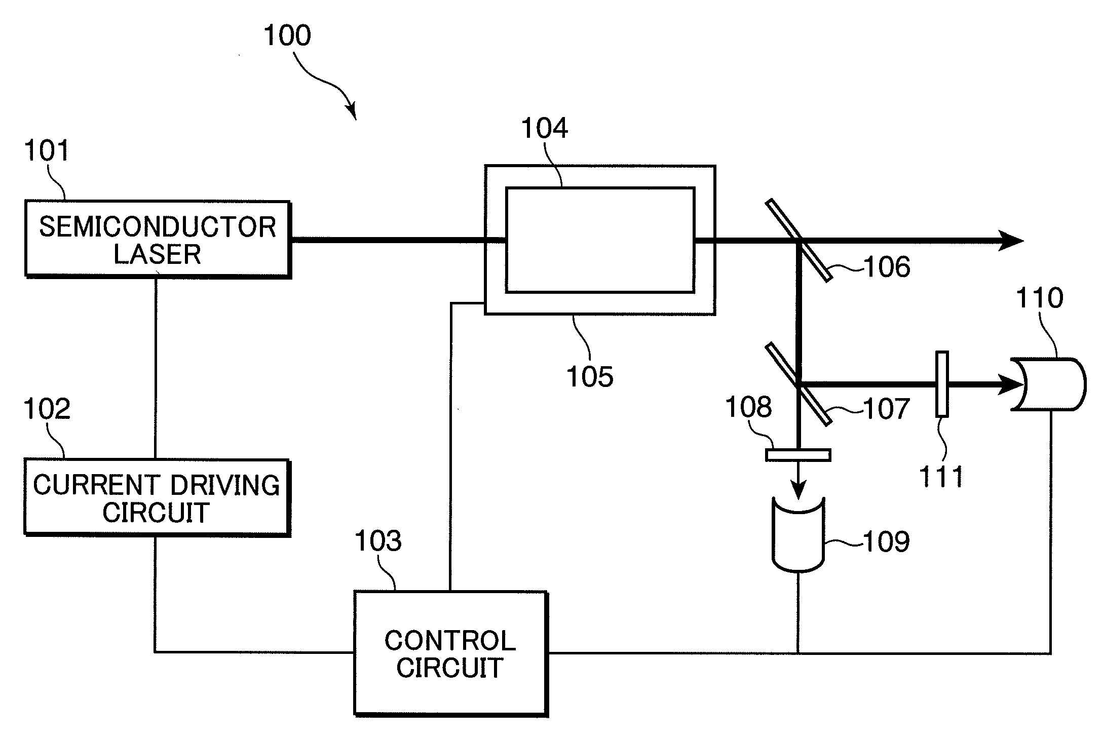
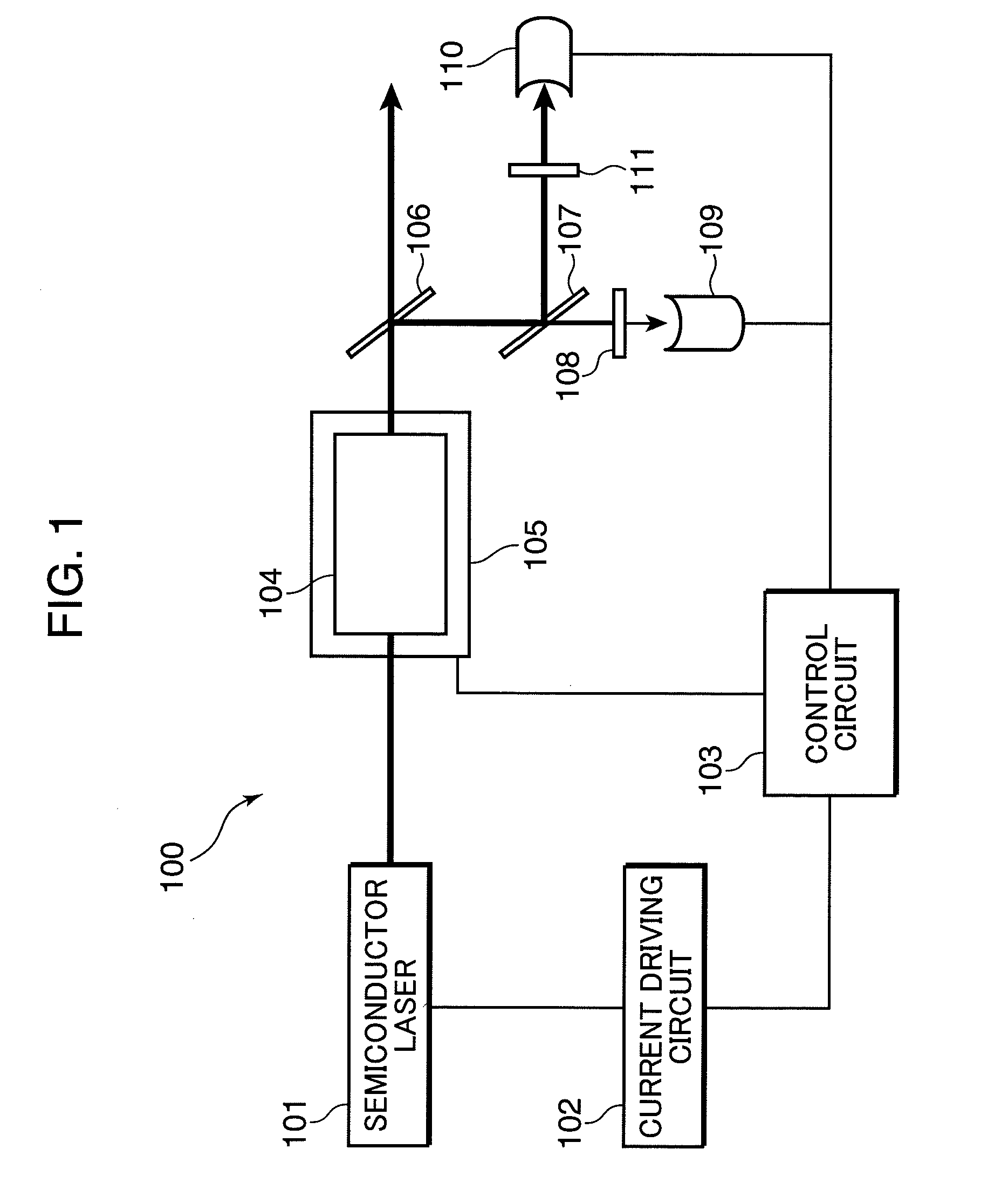
[0044]FIG. 1 is a schematic diagram showing an arrangement of a laser light source in accordance with the first embodiment of the invention. In the following, there is described a laser light source, functioning as a wavelength conversion device, in accordance with the first embodiment of the invention referring to FIG. 1.

[0045]A laser light source 100 shown in FIG. 1 includes a semiconductor laser 101, a current driving circuit 102, a control circuit 103, a wavelength converting element 104, a heater 105, a light separating mirror 106, a light separating mirror 107, a wavelength selecting filter 108, a photodiode 109, a photodiode 110, and a wavelength selecting filter 111.

[0046]The semiconductor laser 101 outputs excitation light with a current from the current driving circuit 102. The outputted excitation light is incident into the wavelength converting element 104, and a part of the excitation light is converted into wavelength converted light. Laser light emitted from the wavel...

second embodiment

(Second Embodiment)

[0075]FIG. 7 is a schematic diagram showing an arrangement of a laser light source in accordance with the second embodiment of the invention. In the following, a laser light source, functioning as a wavelength conversion device, in accordance with the second embodiment is described referring to FIG. 7.

[0076]A laser light source 100a shown in FIG. 7 includes a semiconductor laser 101, a current driving circuit 102, a control circuit 103, a heater 105, a quasi phase matching wavelength converting element 701, a light separating coat 702, a light separating mirror 703, a photodiode 704, an anti-reflective coat 705, and a beam stopper 706.

[0077]Similarly to the first embodiment, the semiconductor laser 101 generates excitation light with a current from the current driving circuit 102. In this embodiment, excitation light is incident into the quasi phase matching wavelength converting element (hereinafter, also called as “wavelength converting element”) 701. In the inc...

third embodiment

(Third Embodiment)

[0111]FIG. 15 is a schematic diagram showing an arrangement of a laser light source in accordance with the third embodiment of the invention. In the following, a laser light source, functioning as a wavelength conversion device, in accordance with the third embodiment of the invention is described referring to FIG. 15.

[0112]Similarly to the first and the second embodiments, a laser light source 100e shown in FIG. 15 is constructed in such a manner that a semiconductor laser 101 outputs excitation light with a current from a current driving circuit 102. Similarly to the second embodiment, excitation light is incident into a quasi phase matching wavelength converting element 701 to generate output light and reference light, and the output of reference light is monitored by a photodiode 704. Also, the output light is incident into a light splitting mirror 1001 for reflecting about 1% of output light, and the reflected output light is incident into a filter 1002 for ab...


PUM

PropertyMeasurementUnit
wavelengthaaaaaaaaaa

Abstract

A laser light source (100) includes a semiconductor laser (101), a wavelength converting element (104) made of a non-linear optical crystal for converting excitation light from the semiconductor laser (101) into wavelength converted light having a wavelength different from the wavelength of the excitation light, a photodiode (109) for measuring a part of the wavelength converted light to be emitted from the wavelength converting element (104) as output light, a photodiode (110) for measuring the excitation light to be emitted from the wavelength converting element (104), and a control circuit (103), wherein the control circuit (103) simultaneously performs an output constant control of making the intensity of the wavelength converted light constant, using a current driving circuit (102), and a temperature control of adjusting the temperature of the wavelength converting element (104), using a heater (105).

Description

TECHNICAL FIELD[0001]The present invention relates to a laser light source including a wavelength converting element for performing wavelength conversion utilizing a non-linear optical effect, and a method for controlling the laser light source, and also relates to an image display apparatus and a processing apparatus incorporated with the laser light source.BACKGROUND ART[0002]Laser light is used in various fields such as measuring apparatuses, medical apparatuses, processing apparatuses, and display apparatuses, not to mention communications apparatus and optical recording apparatuses. A semiconductor laser is used as a primary light source in these fields in view of control feasibility and its small size.[0003]Among the above light sources, a semiconductor laser for stably generating light of a wavelength in a visible region from 0.5 μm to 0.6 μm has not been realized. A semiconductor laser for generating light of a wavelength in a mid infrared region of 2 μm or more is required ...

Claims


Application Information

Patent Timeline
Patent Type & Authority Applications(United States)
IPC IPC(8): G02F1/35
CPCG02B27/102G02B27/149G02F1/133621G02F1/3544G02F1/3558G02F2001/3548H04N9/3129H04N9/3161H04N9/3194G02F1/3548
Inventor KUSUKAME, KOICHIFURUYA, HIROYUKIMIZUSHIMA, TETSUROYAMAMOTO, KAZUHISAKADOWAKI, SHINICHI
Owner PANASONIC CORP
Why Eureka
Try Eureka