Unlock instant, AI-driven research and patent intelligence for your innovation.
Switching controller and switching control system for circuit breaker
Inactive Publication Date: 2010-05-06
KK TOSHIBA
View PDF8 Cites 9 Cited by
Summary
Abstract
Description
Claims
Application Information
AI Technical Summary
This helps you quickly interpret patents by identifying the three key elements:
Problems solved by technology
Method used
Benefits of technology
Benefits of technology
[0016]The present invention is proposed for solving the above mentioned problems, and an object is to provide a switching controller for circuit breaker and a switching control system for circuit breaker that can implement cost saving and space saving, even if switching of a circuit breaker in a lower branch system, such as a power distribution system, is controlled. Another object is to provide a switching controller for circuit breaker and a switching control system for circuit breaker which can be easily connected with such external equipment as a personal computer without using dedicated software at the work site or from a remote place, and can perform efficient maintenance and data collection.
[0019]As a result of using the present invention, one switching controller for circuit breaker can control switching for a plurality of circuit breakers, even if circuit breakers in a lower branch system, such as a power distribution system, are used, so it is unnecessary to install the switching controllers of the same number as that of many circuit breakers, and a switching controller for circuit breaker and switching control system for circuit breaker, that can save cost and save space, can be provided.
Problems solved by technology
However if the switching controller for circuit breaker is used for a circuit breaker in a lower branch system, such as a power distribution system, using one switching controller for one circuit breaker, often causes a cost problem.
Also in a power station in a lower branch system, such as a power distribution system, the installation space for a circuit breaker is often limited, so installing switching controllers of the same number as that of the circuit breakers is difficult.
As a result of using this prior art, a personal computer in which the dedicated software is not installed cannot be connected to the switching controller for circuit breaker, which is very inconvenient to use in terms of storage and management of various acquired data.
Also in the case of the switching controller for circuit breaker according to Non-Patent Document 1, an RS-232C interface is used to connect with the personal computer, which is based on the local connection at the work site, and is inconvenient for remote control.
If remote control is required, a modem must be connected to the personal computer so as to be connected with the switching controller for circuit breaker via a telephone line, which is not only inconvenient to use but also communication speed is slow and operation is inefficient.
Another problem is that only one switching controller for circuit breaker can be connected to one personal computer, which means that in order to perform maintenance and acquire various data for switching controllers for circuit breaker installed in a plurality of circuits, a connection switching operation is generated, and the operation efficiency deteriorates.
Method used
Image
Click on the blue label to locate the original text in one second.
Reading with bidirectional positioning of images and text.
Examples
first embodiment
[0033][1. First Embodiment]
[0034][1.1 Configuration]
[0035][1.1.1 General Configuration]
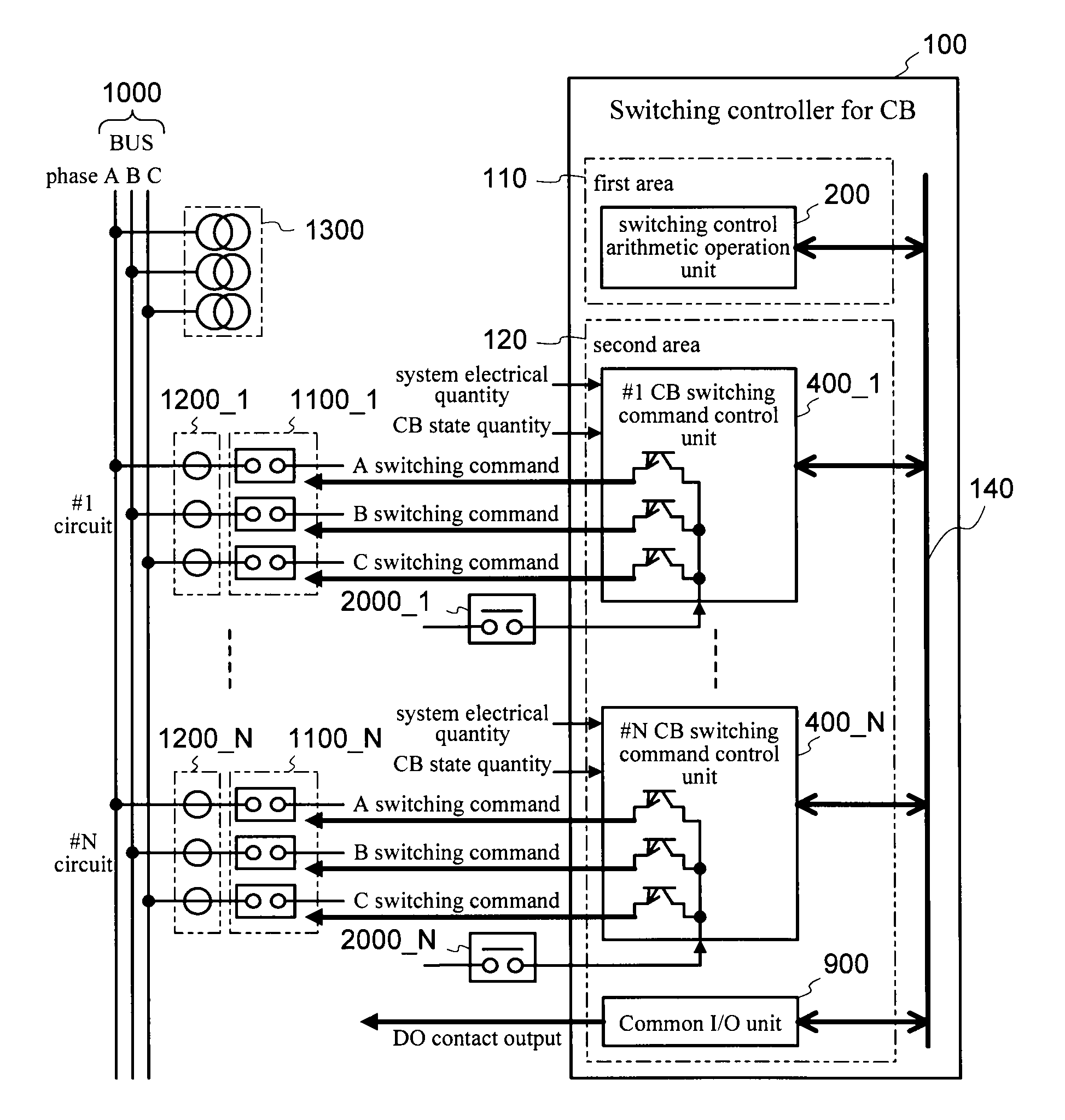
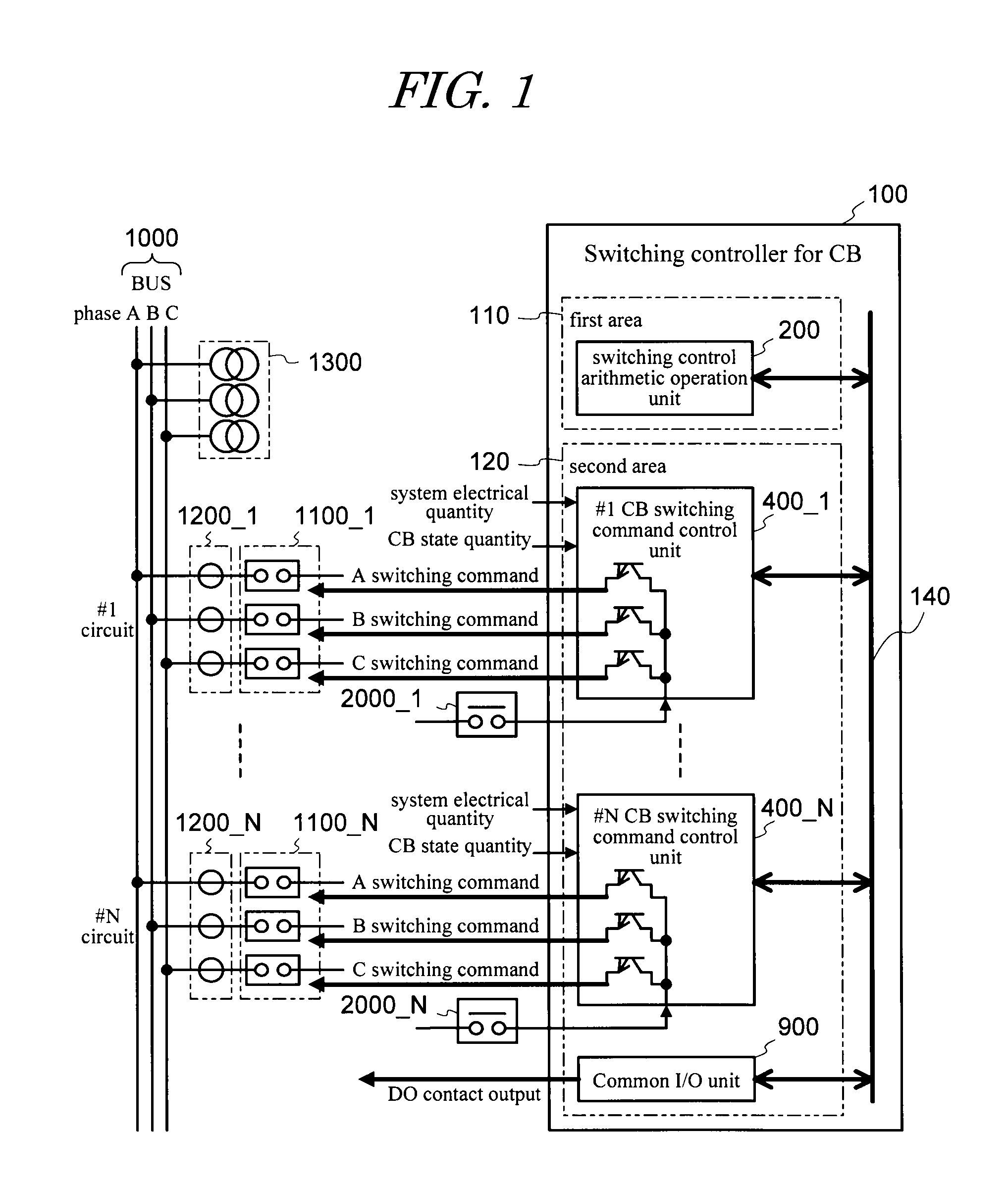
[0036]The configuration of the entire system of a switching controller for circuit breaker and peripheral circuits thereof according to the first embodiment will be described first with reference to FIG. 1.
[0037]As FIG. 1 shows, 100 denotes a switching controller for circuit breaker of the present invention, and 1000 denotes a main circuit, which is constituted of a bus, power transmission circuits from circuit #1 to circuit #N, a transformer circuit and a phase modifier circuit.
[0038]1100 _1 to 1100_N denote single-phase operation-type circuit breakers for 3 phases (hereafter simply circuit breaker unless otherwise specified) corresponding to circuit #1 to circuit #N, 1200_1 to 1200_N denote current transformers for 3 phases corresponding to circuit #1 to circuit #N, and 1300 denotes a voltagetransformer for 3 phases connected to a bus of a main circuit 1000. Since the switching controller for c...
second embodiment
[0090][2. Second Embodiment]
[0091][2.1 Configuration]
[0092]Configuration of a system of the switching controller for circuit breaker and peripheral circuits thereof according to the second embodiment of the present invention (hereafter switching control system for circuit breaker) will be described next with reference to FIG. 4. As FIG. 4 shows, 100 denotes a switching controller for circuit breaker, 700 denotes a display operation device, and 510 denotes a communication transmission medium, and these aspects, which are characteristics of the second embodiment, will be described herein below. The main circuit 1000, circuit breaker 1100, current transformer 1200 and voltagetransformer 1300, which have the same configuration as the first embodiment, are denoted with the same reference symbols, and description thereof is omitted.
[0095]Major components of the switching controller for circuit break...
third embodiment
[0131][3. Third Embodiment]
[0132][3.1 Configuration]
[0133]The configuration of the system of the switching controller for circuit breaker and peripheral circuits thereof according to the third embodiment of the present invention (hereafter switching control system for circuit breaker) will be described next with reference to FIG. 6. As FIG. 6 shows, 100i to 100M denote switching controllers for circuit breaker, 700 denotes a display operation device, and 500 denotes a communication network, and this aspect, which is a characteristic of the third embodiment, will be described herein below.
[0134]The other main circuits 1000i to 1000M, circuit breakers 1100i_1 to 1100M_N, current transformers 1200i_1 to 1200M_N, and voltage transformers 1300i to 1300M, which have the same configurations as the first embodiment, are denoted with the same reference symbols, and description thereof is omitted. The suffixes i to M attached to the circuit breakers 1100i_1 to 1100M_N, current transformers 12...
PUM
Abstract
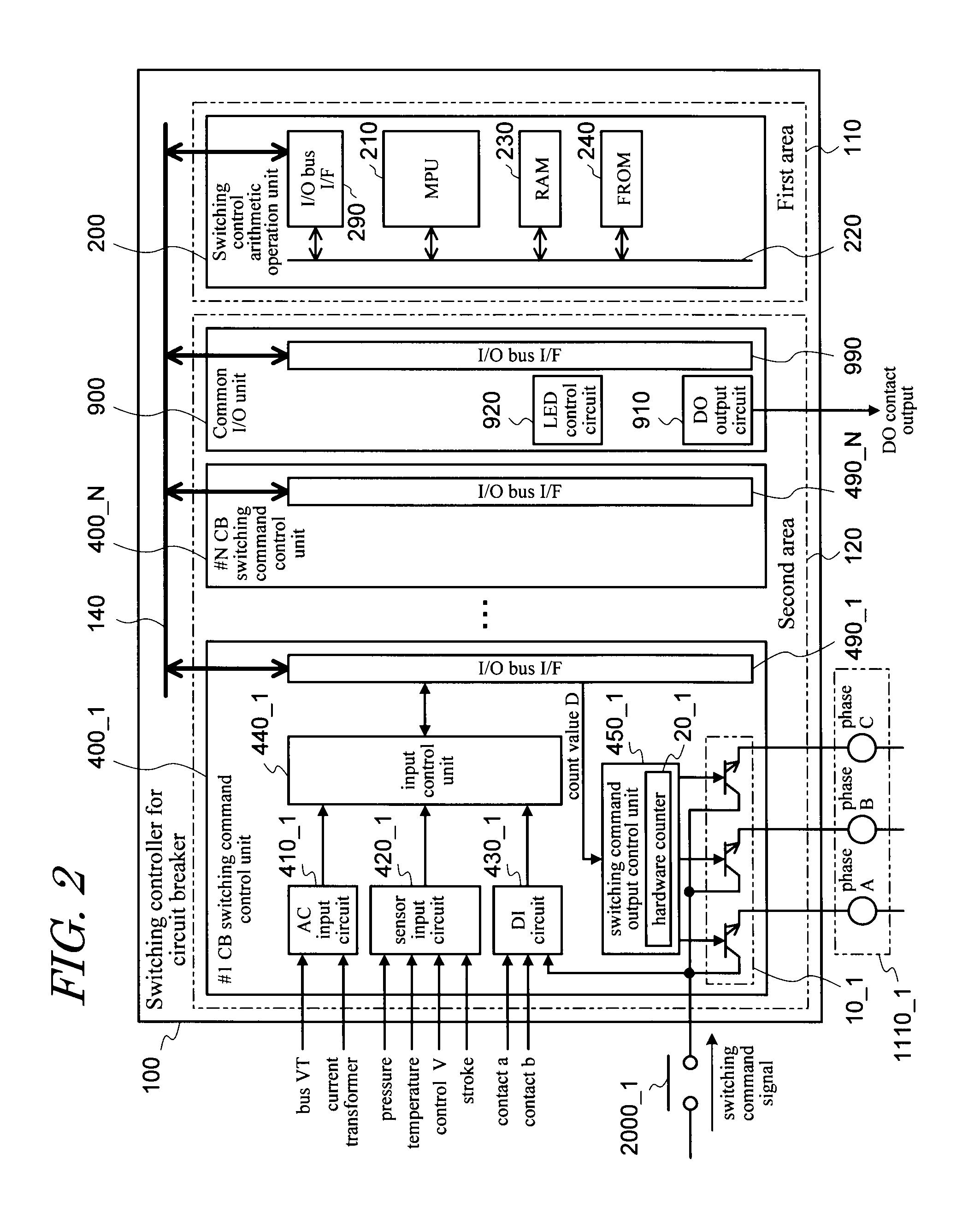
The MPU for switching control arithmetic operation 210 in the switching control arithmetic operation unit 200 performs arithmetic operations to determine a predetermined delay time (synchronous delay count value D) for each circuit breaker 1100. The synchronous delay count value is sent to each switching command control unit 400 of the corresponding circuit breaker. The hardware counter 20 of the switching command output control unit 450, for the switching command signal received from the superordinate device 2000, counts the synchronous delay count value D, which is the delay time. When the semiconductor switch of the switching command output unit 10 turns ON after counting completes, the switching command signal (circuit breaker drive current) after the synchronous switching control is output to the circuit breaker drive coil 1110 of the circuit breaker 1100. A switching controller for circuit breaker and a switching control system for circuit breaker are provided, which can implement cost saving and space saving, even if switching of a circuit breaker in a lower branchsystem, such as a power distribution system, is controlled.
Description
BACKGROUND OF THE INVENTION[0001]1. Field of the Invention[0002]The present invention relates to a technology to control switching of a circuit breaker, and more particularly to a switching controller for circuit breaker of which switching can be controlled, without increasing cost and installation space, even if the circuit breaker is in a lower branchsystem.[0003]2. Description of the Related Art[0004]In a device for controlling switching of a power circuit breaker, a method for controlling the opening / closing timing of the circuit breaker, so as not to generate transient phenomena in a system and power apparatus, has been proposed (e.g. see Patent Document 1). In the power switching controller according to prior art disclosed in Patent Document 1, the object is to prevent the generation of transient phenomena, which negatively influences the system and apparatus, under any switching conditions of the circuit breaker.[0005]In addition to this prior art, a device for controlling t...
Claims
Application Information
Patent Timeline
Application Date:The date an application was filed.
Publication Date:The date a patent or application was officially published.
First Publication Date:The earliest publication date of a patent with the same application number.
Issue Date:Publication date of the patent grant document.
PCT Entry Date:The Entry date of PCT National Phase.
Estimated Expiry Date:The statutory expiry date of a patent right according to the Patent Law, and it is the longest term of protection that the patent right can achieve without the termination of the patent right due to other reasons(Term extension factor has been taken into account ).
Invalid Date:Actual expiry date is based on effective date or publication date of legal transaction data of invalid patent.
