Light tube

a technology of light tubes and led light tubes, applied in the direction of lighting support devices, lighting and heating apparatus, coupling device connections, etc., can solve the problems of insufficient structure strength, difficult and time-consuming replacement of led light tubes, and insufficient heat dissipation capability of light tubes, so as to improve the light-emitting efficiency and lifespan of the first light-emitting device and the second light-emitting device. , the effect of improving the heat dissipation

Inactive Publication Date: 2010-05-06
EVERLIGHT ELECTRONICS
View PDF33 Cites 16 Cited by
  • Summary
  • Abstract
  • Description
  • Claims
  • Application Information

AI Technical Summary

Benefits of technology

[0031]In the light tube according to the embodiment of the present invention, a separation space is kept between the first line of light-emitting devices and the second line of light-emitting devices so that the light source is more dispersed. Accordingly, the lights emitted by the first line of light-emitting devices and the second line of light-emitting devices are more uniform after they passes through the light transmissive cover. Thus, the light tube is suitable for illumination of general purpose. Moreover, the existence of the separation space allows the heat produced by the first line of light-emitting devices and the second line of light-emitting devices to be more dispersed, so that the heat dissipation capability of the light tube can be improved. Namely, the temperature of the first line of light-emitting devices and the second line of light-emitting devices is reduced, and accordingly the light emitting efficiency and lifespan of the first light-emitting devices and the second light-emitting devices are improved.

Problems solved by technology

However, the fastener used for fastening the LED light tube is not conductive.
As a result, the assembly and disassembly of the LED light tube are very inconvenient and it is very difficult and time-consuming to replace the LED light tube.
However, through such a method, the problem of insufficient structure strength may be produced, and the parallelism between the two electrode poles may be adversely affected.
Besides, when the electrode poles are welded onto the circuit board, it is very difficult to maintain the parallelism between the two electrode poles.
Thereby, such a design may reduce the production yield.
Since LED is highly directional, the light emitted by a LED light tube may be too concentrated and accordingly the LED light tube may not be suitable for illumination of general purpose if the disposition of the LED is highly centralized.
Besides, if the disposition of LED is too centralized, the heat produced by the LED cannot be dissipated efficiently.
As a result, the heat dissipation efficiency of the LED light tube is reduced, and accordingly the light emitting efficiency and lifespan of the LED light tube are reduced.

Method used


Image

  • Light tube
  • Light tube
  • Light tube

Examples


Embodiment Construction

[0049]Reference will now be made in detail to the present preferred embodiments of the invention, examples of which are illustrated in the accompanying drawings. Wherever possible, the same reference numbers are used in the drawings and the description to refer to the same or like parts.

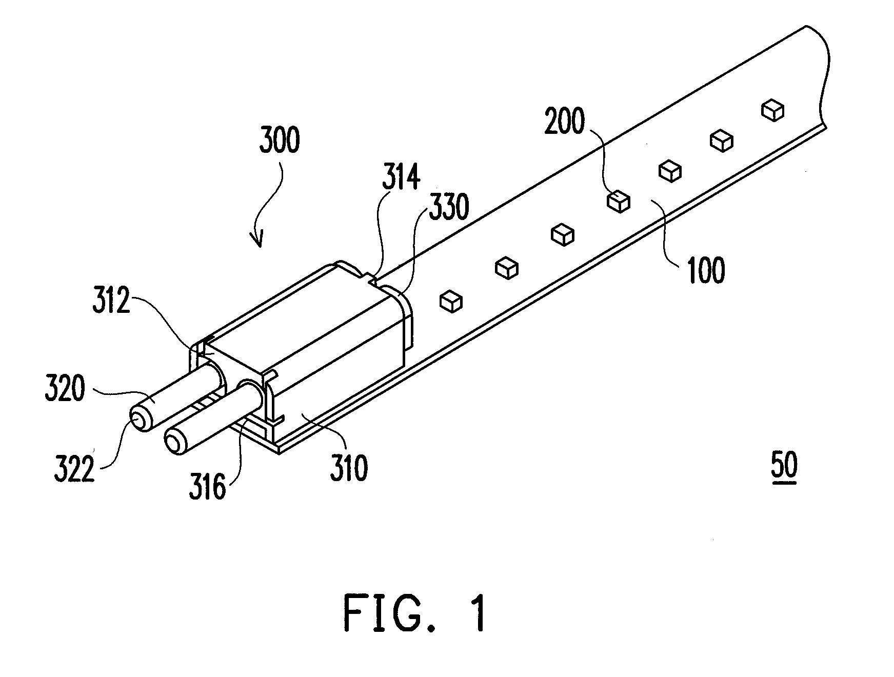
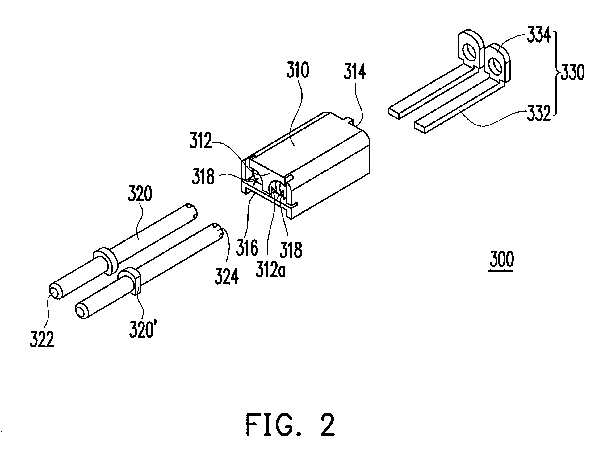
[0050]FIG. 1 is a diagram of a light source module according to an embodiment of the present invention. FIG. 2 is an exploded view of a connector in the light source module in FIG. 1. Referring to FIG. 1 and FIG. 2, the light source module 50 includes a carrier 100 and a plurality of light-emitting devices 200, wherein the light-emitting devices 200 are disposed on the carrier 100. In the present embodiment, the carrier 100 may be a circuit board, and the light-emitting devices 200 may be light-emitting diodes (LEDs). In the present embodiment, the light-emitting devices 200 are arranged on the circuit board along a straight reference line. In the present embodiment, the light source module 50 furthe...


PUM


Abstract

A light tube including a heat sink, a light transmissive cover disposed on the heat sink, and at least one light source module is provided. A containing space is formed between the heat sink and the light transmissive cover. The light source module includes a carrier, a plurality of first light-emitting devices, a plurality of second light-emitting devices, and a plurality of non-light-emitting passive devices. The carrier is disposed on the heat sink. The first light-emitting devices are arranged on the carrier along a first straight reference line to form a first line of light-emitting devices. The second emitting devices are arranged on the carrier along a second straight reference line to form a second line of light-emitting devices. The non-light-emitting passive devices are disposed on the carrier and between the first and second lines of light-emitting devices and electrically connected to the first and the second light-emitting devices.

Description

CROSS-REFERENCE TO RELATED APPLICATION[0001]This application claims the priority benefits of Taiwan application serial No. 97142572, filed on Nov. 4, 2008 and Taiwan application serial No. 98106471, filed on Feb. 27, 2009. The entirety of each of the above-mentioned patent applications is hereby incorporated by reference herein and made a part of this specification.BACKGROUND OF THE INVENTION[0002]1. Field of the Invention[0003]The present invention generally relates to a light source, and more particularly, to a light tube.[0004]2. Description of Related Art[0005]The power and light intensity of light-emitting diode (LED) have been increased along with the development of semiconductor technology. Moreover, LED has been broadly applied to different products (for example, illumination devices, traffic lights, displays, and optical mice, etc) and is about to replace the conventional fluorescent light tube due to its many advantages, such as low power consumption, long lifespan, enviro...

Claims


Application Information

Patent Timeline
Patent Type & Authority Applications(United States)
IPC IPC(8): F21S4/00
CPCF21V23/02F21K9/27F21Y2103/10F21Y2115/10
Inventor PEI, CHIEN-CHANGCHEN, YI-HUNG
Owner EVERLIGHT ELECTRONICS
Why Eureka
Try Eureka