X-ray image analyzing system and program

a x-ray image and image analysis technology, applied in the field of x-ray image analyzing system and program, can solve the problems of inability to draw minute osteophytes, minute bone erosion, and minute decreases of trabeculae, and achieve the effect of little blurring

Inactive Publication Date: 2010-05-06
KONICA MINOLTA MEDICAL & GRAPHICS INC
View PDF3 Cites 33 Cited by
  • Summary
  • Abstract
  • Description
  • Claims
  • Application Information

AI Technical Summary

Benefits of technology

[0071]According to the inventions of claims 1 and 15, it is possible to compute an appropriate trabecular bone index and a bone-flesh boundary index from a same X-ray image of a subject of a hand, and the early diagnoses of an arthropathy and an osteoporosis becomes possible,
[0072]According to the inventions of claims 2 and 16, because an X-ray intensity profile to the positions in each direction of two or more intersecting directions is acquired from the image data in a trabecular bone index computing region and a trabecular bone index is computed on the basis of the X-ray intensity profile, trabecular bone indices including fewer individual differences can be computed. Although the reason why the trabecular bone indices including fewer individual differences can be obtained includes un-elucidated parts, it can be conjectured that the reason is because the differences of the numbers of the trabeculae owing to the directions depend on the degree of progress of the bone diseases more than individual differences although the numbers of trabeculae greatly depend on the individual differences.
[0073]Moreover, according to the inventions of claims 8 and 22, because an X-ray intensity profile to the positions of a bone portion in the neighborhood of a bone-flesh boundary in a subject is acquired from the image data in a bone-flesh boundary index computing region and a bone-flesh boundary index is computed from the X-ray intensity profile, the bone-flesh boundary index having a strong correlation with the progress of a disease can be obtained. The reason why the bone-flesh boundary index having a strong correlation with the progress of a disease can be obtained includes an un-elucidated part. The image that can well reproduce a bone portion in the neighborhood of a bone-flesh boundary can be obtained by a multiplier effect of a sufficient phase contrast effect as mentioned above, the clarification of a boundary having an X-ray refractive index difference, the capability of the delineation of the minute structure of a subject owing the an expansion imaging effect including little blurring, and the obtainability of a strong absorption contrast optimum for an X-ray imaging image of a hand as a subject by a low energy X-ray imaging effect. In a disease such as a bone erosion and an osteophyte, the occurrence of the unevenness of the external form of a bone in the neighborhood of a bone-flesh boundary can be conjectured to have a strong with the progress of the disease in such a way that the bone quantity of a bone portion in the neighborhood of a bone-flesh boundary falls and the gradient of an intensity profile of the X-rays to the positions of the image data of a bone in the neighborhood of the bone-flesh boundary bone falls.

Problems solved by technology

But, the conventional simple X-ray imaging with no modifications can delineate large osteophytes, large bone erosion, and remarkable decreases of trabeculae, but cannot draw minute osteophytes, minute bone erosion, and minute decreases of trabeculae.
Consequently, the X-ray images obtained by the conventional simple X-ray imaging have been impossible to enable the acquirement of the indices indicating the useful states of trabeculae and the indices indicating bone-flesh boundaries.

Method used


Image

  • X-ray image analyzing system and program
  • X-ray image analyzing system and program
  • X-ray image analyzing system and program

Examples


Embodiment Construction

[0172]In the following, the best mode for implementing the present invention will be described with reference to the accompanying drawings.

[0173]Incidentally, the description of the present column shows the mode that the inventor recognizes to be best for implementing the present invention, and the description includes the expressions that seem to conclude or define the range of the invention and the terms used in claims apparently. But those expressions are those for specifying the mode that the inventor recognizes to be best to the last, and are not the ones that specify or limit the range of the invention and the terms used in the claims. Moreover, the range of the invention is not limited to the shown examples.

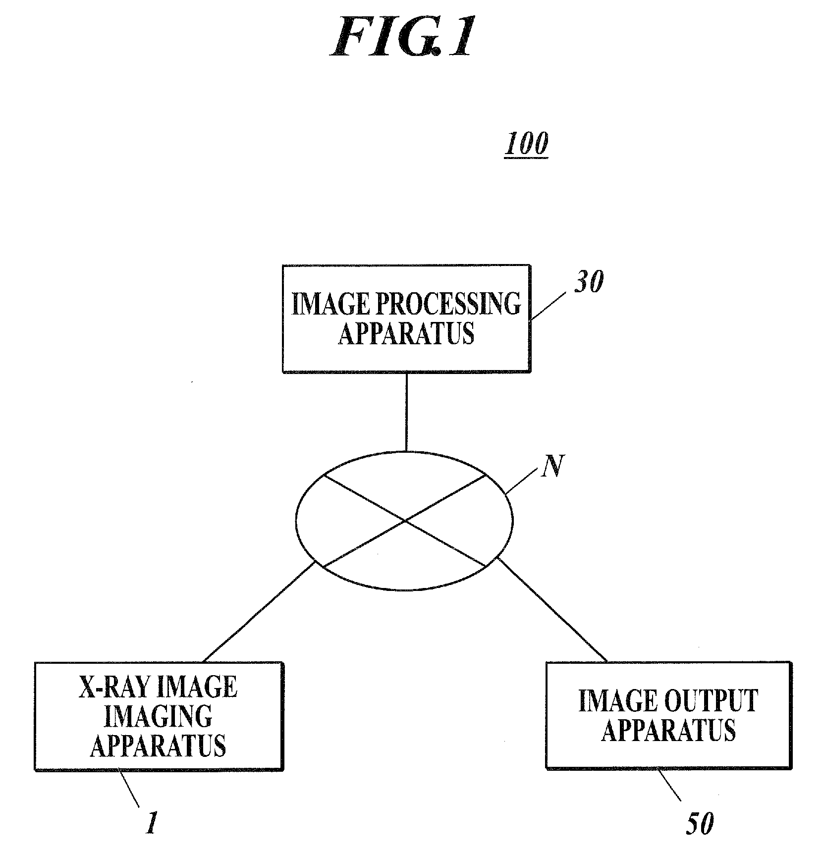
[0174]FIG. 1 shows a configuration example of an X-ray image analyzing system 100 in a present embodiment. In the present embodiment, the X-ray image analyzing system 100 is composed of an X-ray image imaging apparatus 1 to generate an image of an imaging object by radiati...


PUM

PropertyMeasurementUnit
diameteraaaaaaaaaa
diameteraaaaaaaaaa
focus sizeaaaaaaaaaa

Abstract

An X-ray image analyzing system, including:
an X-ray source for radiating an X-ray; an X-ray detector for detecting an X-ray image radiated onto an x-ray image detection surface, wherein phase contrast X-ray simple imaging is capable of being performed determining a trabecular bone index computing region, computing a trabecular bone index indicating a state of a trabecula from image data in the trabecular bone index computing region, determining a bone-flesh boundary index computing region by a second region determination method different from the first region determination method, and computing a bone-flesh boundary index indicating smoothness of a bone-flesh boundary from image data in the bone-flesh boundary index computing region.

Description

TECHNICAL FIELD[0001]The present invention relates to an X-ray image analyzing system and a program.BACKGROUND ART[0002]It is said that the symptoms of arthropathy advance from the swelling of a joint, the inflammation of a synovial membrane, the breakages of a cartilage and a ligament in the neighborhood of the joint, and a minute breakage of a bone in the neighborhood of the joint (the formation of minute osteophytes and bone erosion, the decrease of trabeculae in the neighborhood of the joint, or the like) to a sightable breakage of a bone in the neighborhood of the joint in a simple X-ray image, the minimization of a joint fissure, and the luxation and the ankylosis of the joint. Accordingly, if indices indicating the degrees of the breakages of a cartilage and a ligament in the neighborhood of a joint and a minute breakage of a bone in the neighborhood of the joint can be obtained at the stage of the aforesaid incipient breakages, then it is conceivable that the indices are use...

Claims


Application Information

Patent Timeline
Patent Type & Authority Applications(United States)
IPC IPC(8): G06K9/00G01N23/06
CPCA61B6/469A61B6/484A61B6/505G06T7/0012G06T2207/10116G06T2207/30008A61B6/4494A61B6/4021
Inventor TAMAKOSHI, YASUAKI
Owner KONICA MINOLTA MEDICAL & GRAPHICS INC
Why Eureka
Try Eureka