Phototherapy garment

a technology for garments and phototherapy, applied in the field of garments, can solve the problems of increasing the cost of treatment, prolonging or restricting treatment, and reducing the effect of treatment effect, so as to head exposure, reduce the risk of eye damage, and reduce the effect of radiation therapy

Inactive Publication Date: 2010-05-06
THE BOARD OF TRUSTEES OF THE UNIV OF ARKANSAS
View PDF3 Cites 36 Cited by
  • Summary
  • Abstract
  • Description
  • Claims
  • Application Information

AI Technical Summary

Benefits of technology

[0013]The present invention has been carefully designed to mitigate these side effects. Specifically, with regard to Method 1, the present invention provides therapeutic irradiance through a fiber optic system that does not transmit heat. Side effects that currently cause serious concern and monitoring such as increased body temperature and subsequent dehydration are not a factor with the present invention. Similarly, because the light is contained within the bodysuit and directed only to the arms, legs, and torso, dangers to the eyes and exposure of light to the head are avoided. The present invention is preferably cordless and portable, allowing for proper treatment in transit, at home or in any location.
[0014]Likewise, the present invention utilizes the safety of a fiber optic design, but eliminates the mobility and safety concerns noted with Method 2 treatments. Therapeutic light is always in direct contact with the skin and is completely contained within the bodysuit shell. A reflective lining redirects irradiance toward the skin so no energy is wasted. The system is cordless and portable allowing for continuous, uninterrupted treatment at any location. The light system used to provide required irradiance is operated using high-output LEDs which do not produce heat, eliminating potential fire hazards or overheating of the unit or patient.
[0015]The device disclosed in Vreman patent indicates an electronic circuitry inside the garment, close to the infant's skin which could be exposed to moisture. The present invention avoids this possible safety hazard. The present invention contains no electronic circuitry within the element of the suit unit. All circuitry is contained within a durable, waterproof base unit. Furthermore, while irradiance with the present invention is provided through LEDs, actual propagation of the wavelengths is delivered through side-glow optical fibers. The design of the Vreman device allows for the light panel array to be put into a garment. However, based upon available information within the Vreman patent, the garment may not necessarily be washable and may render regular clothing unusable after treatment has commenced. The present invention preferably has a shell which is washable, inexpensive to manufacture, and may be discarded after treatment. It is designed to fit directly under regular clothing.

Problems solved by technology

Method 1 can only be provided while the patient is in a hospital setting, a situation which significantly increases the cost of treatment.
As the intense light may damage the infant's eyes, they are covered with eye patches, a requirement that may lead to conjunctivitis.
The optical fiber pad provides treatment to a limited surface area, potentially prolonging or limiting treatment.
Due to the high heat produced by this lighting system, a fan must operate within the unit continually or risk overheating of the unit and a potential fire hazard.
As a result of this design, mobility is extremely limited.
However, based upon available information within the patent, the garment may not necessarily be washable and may render regular clothing unusable after treatment has commenced.

Method used


Image

  • Phototherapy garment
  • Phototherapy garment
  • Phototherapy garment

Examples


Embodiment Construction

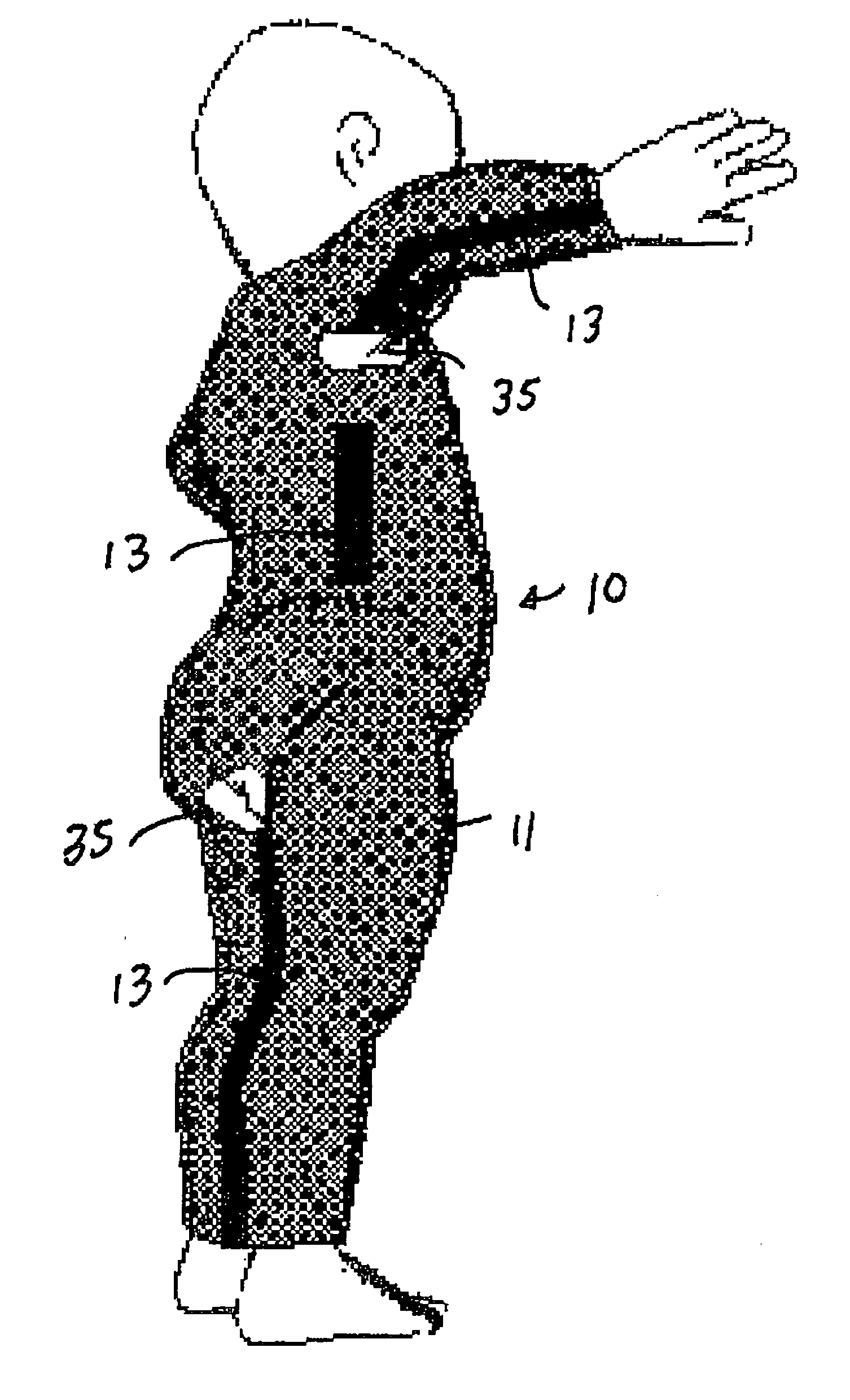
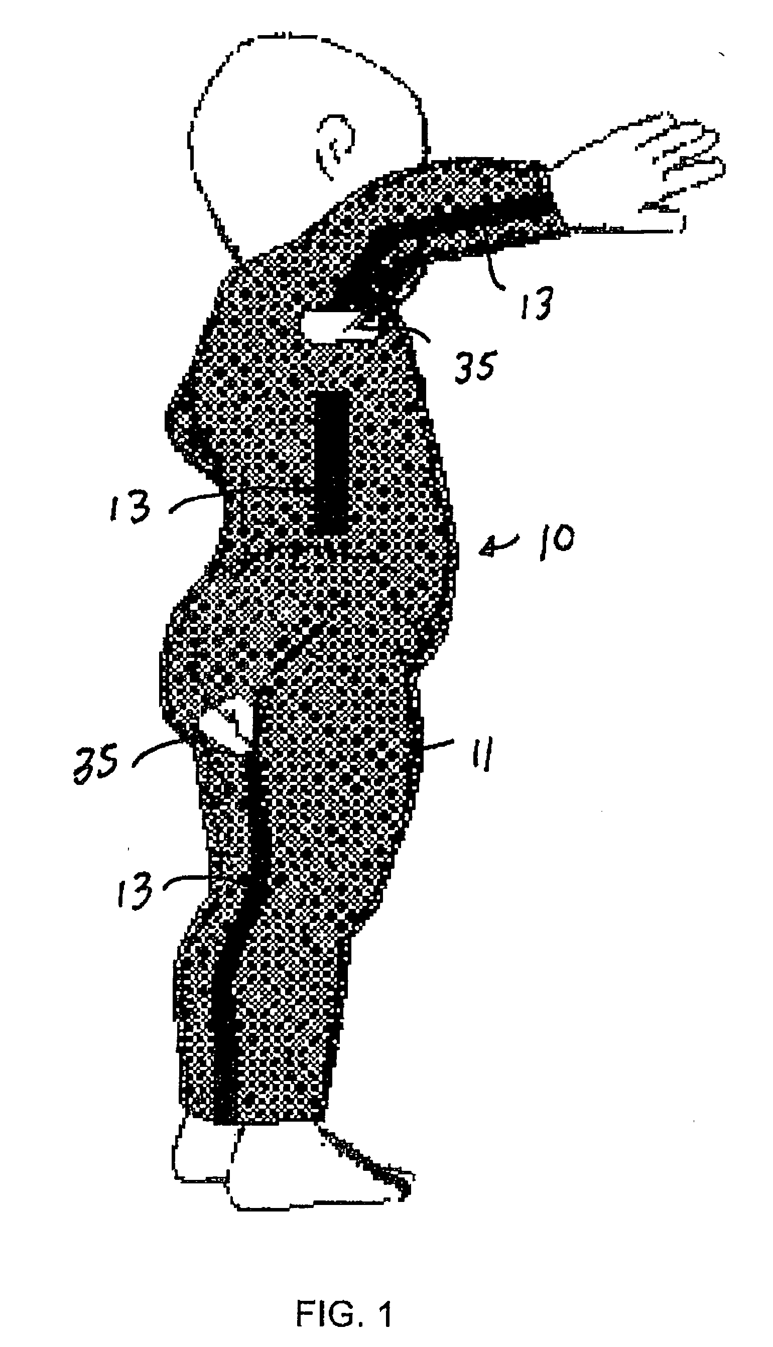
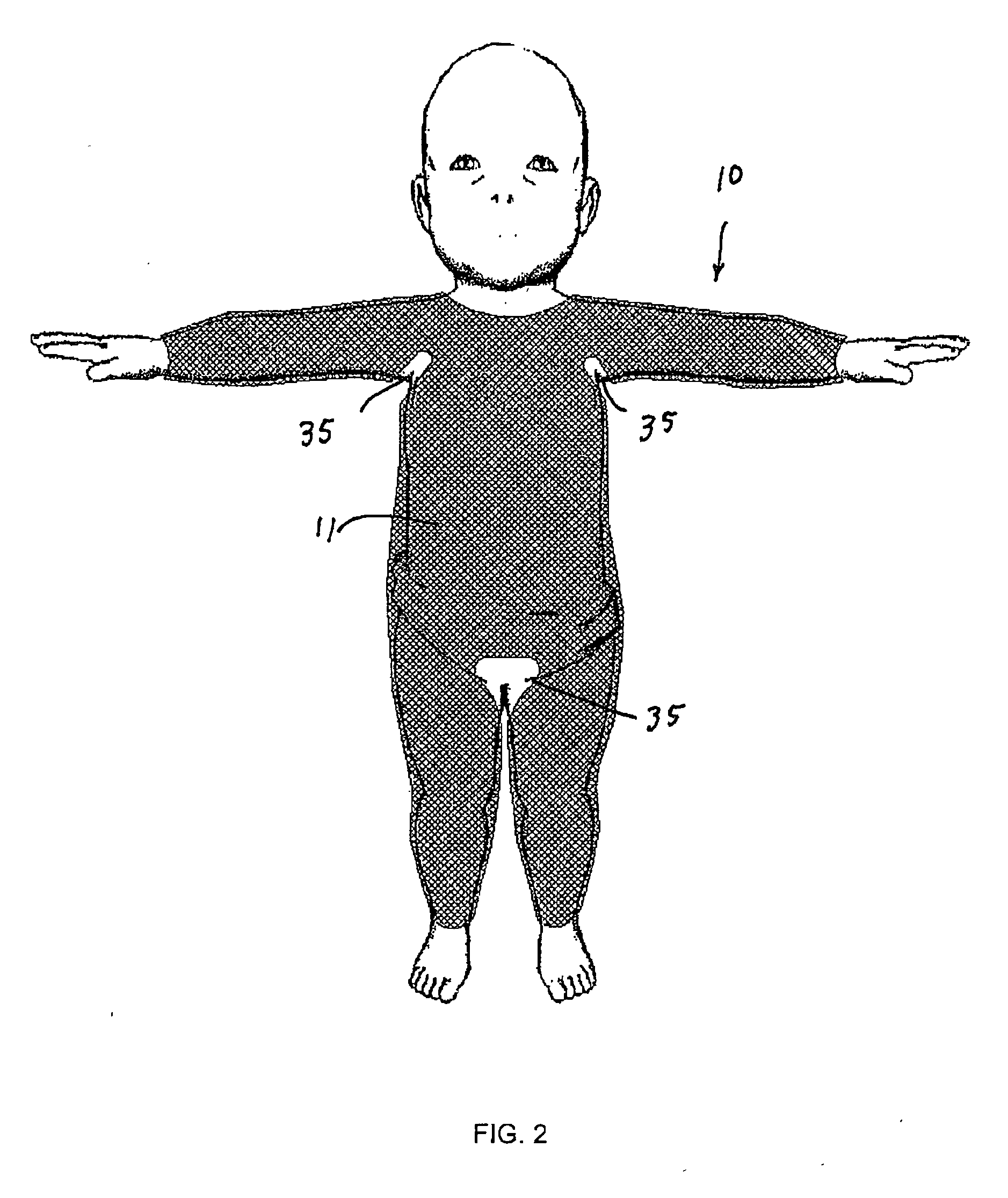
[0025]With reference to FIGS. 1-5, the preferred embodiments of the present invention may be described.

[0026]As shown in FIGS. 1 and 2, the present invention includes a form-fitting bodysuit 10 for phototherapy having a shell 11 made from a stretchable, washable material, such as polyester / spandex, covering the arms, legs, and torso of the patient. The bodysuit 10 may have open areas 35, for example in the armpit or groin areas, for ventilation. With reference to FIG. 3, a layer of cross-woven side-glow optical fibers 12 which provides phototherapeutic light is disposed within the shell 11 of the bodysuit 10. Acrylic optical fibers available from 3M are suitable for the practice of the present invention. As shown in FIG. 1, the bodysuit 10 has adjustable fasteners 13 along the arms, legs, and torso of the patient to allow for variable sizing and a snug fit. With reference to FIG. 4, light is transmitted into the layer of cross-woven optical fibers 12 from light emitting diodes (“LED...


PUM


Abstract

A phototherapy garment including a form-fitting bodysuit having a shell made from a stretchable, washable material covering the arms, legs, and torso which provides phototherapeutic light via a layer of cross-woven side-glow optical fibers. The bodysuit has an adjustable fastening system along the arms, legs, and torso to allow for variable sizing and a snug fit. Light is transmitted into the fibers via a waterproof base unit that is detachably attached to a housing dock on the side of the bodysuit. The LEDs emit high-intensity light of a wavelength or wavelengths suitable for treatment of various medical conditions. Each wavelength is transmitted separately into a respective one of a series of cross-woven optical fibers. Optionally, a reflective liner within the bodysuit may redirect irradiation from the fibers back toward the skin so no energy is wasted. Another embodiment includes a transparent liner. The base unit includes a power supply that may includes a rechargeable battery. The suit may also include biofeedback and data logging systems.

Description

CROSS-REFERENCE TO RELATED APPLICATIONS[0001]This application claims the benefit of U.S. Provisional Patent Application No. 61 / 198,191 filed Nov. 4, 2008, the disclosure of which is incorporated herein by reference in its entirety.STATEMENT REGARDING FEDERALLY SPONSORED RESEARCH OR DEVELOPMENT[0002]Not applicable.BACKGROUND OF THE INVENTION[0003]1. Field of the Invention[0004]The present invention relates to a garment that provides phototherapy, and in particular, to such a garment that provides treatment of hyperbilirubinemia in infants.[0005]2. Brief Description of the Related Art[0006]Current treatment using phototherapy for reduction of bilirubin includes two basic approaches. Current techniques involve either the placement of an infant in an isolette tank with directed use of high-powered fluorescent lighting, identified herein as “Method 1” or through posterior contact with an optical fiber, identified herein as “Method 2.”[0007]Method 1 can only be provided while the patient ...

Claims


Application Information

Patent Timeline
Patent Type & Authority Applications(United States)
IPC IPC(8): A61N5/06
CPCA61N5/0621A61N2005/0645A61N2005/0652
Inventor PRESSLER, TIFFANY J.MCGEHEE, JR., ROBERT E.KAISER, JEFFREY R.
Owner THE BOARD OF TRUSTEES OF THE UNIV OF ARKANSAS
Why Eureka
Try Eureka