Method and system for controlling a doubly-fed induction machine

Active Publication Date: 2010-05-06
MCGILL UNIV
View PDF7 Cites 15 Cited by
  • Summary
  • Abstract
  • Description
  • Claims
  • Application Information

AI Technical Summary

Problems solved by technology

A major disadvantage of these methods is that they are dependent on machine parameters that change over a time period of machine operation such as, for example, changing rotor resistances due to wear in the brush slip ring contact.

Method used


Image

  • Method and system for controlling a doubly-fed induction machine
  • Method and system for controlling a doubly-fed induction machine
  • Method and system for controlling a doubly-fed induction machine

Examples


first embodiment

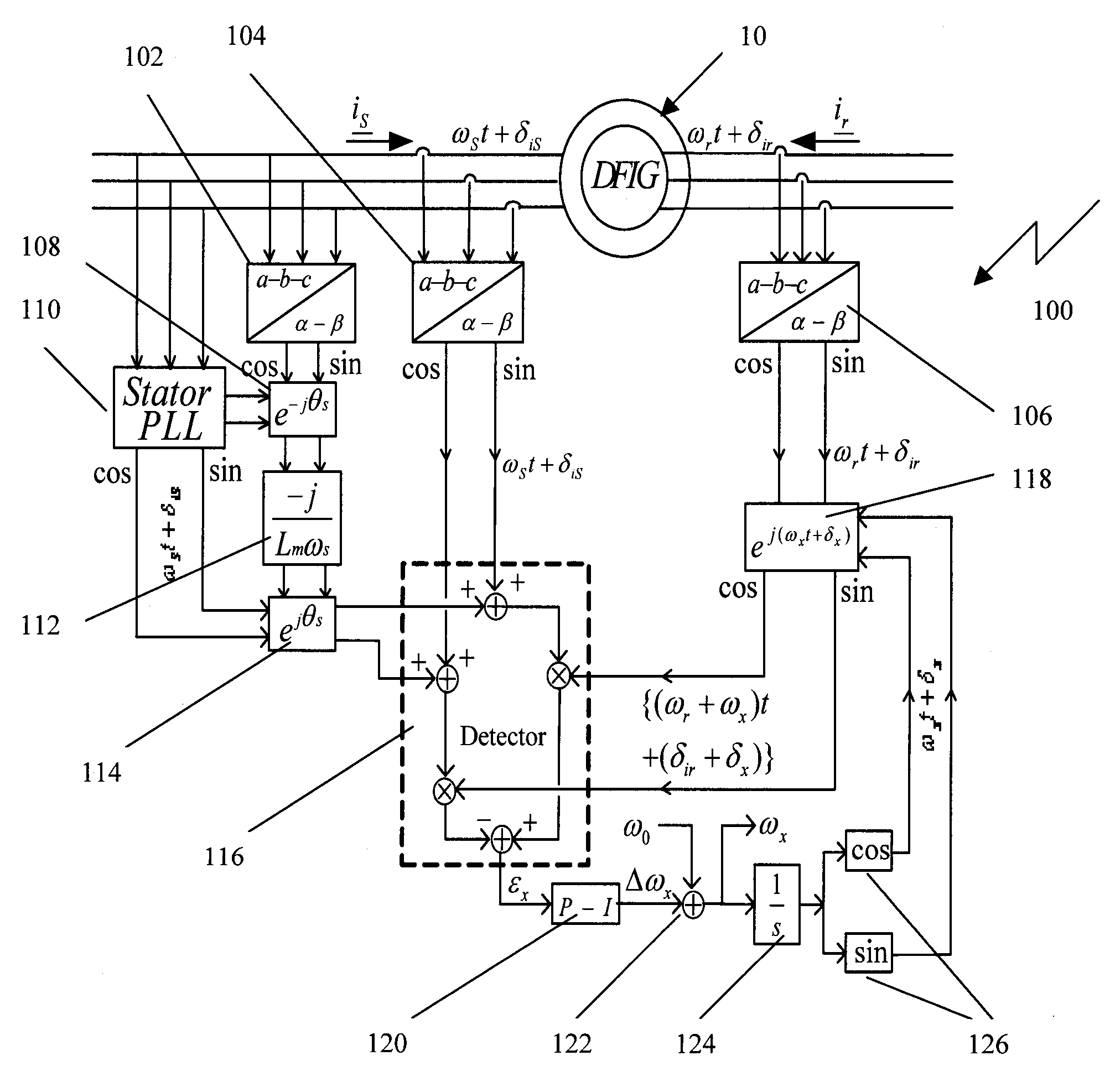
[0062]Referring to FIG. 6, a simplified block diagram of a Rotor Position PLL system 100 according to the invention is shown. The Rotor Position PLL system 100 receives from transducers signals indicative of the 3-phase stator currents, the 3-phase rotor currents, and the 3-phase stator voltages and from the Stator PLL a signal indicative of the phase angle. The output signal is indicative of a rotor angular frequency and position θm=ωmt+δm. The 3-phase a-b-c quantities are converted to 2-phase α-β quantities in coordinate frame transformation blocks 102, 104, and 106 for the stator voltages, the stator currents, and the rotor currents, respectively. FIG. 6 depicts 2-phase information channels with cos(..) and sin(..) symbols under the transformation blocks denoting the channels containing the cosine and the sine of arguments. The arguments are the angles θx=ωxt+δx, θS=ωSt+δS and θr=ωrt+δr for the channels of blocks 126, 104, and 106, respectively.

[0063]The operation of the Rotor Po...

second embodiment

[0075]Referring to FIG. 11, a simplified block diagram of a Rotor Position PLL system 300 according to the invention is shown. The Rotor Position PLL 300 is similar in structure and function to the Rotor Position PLL 100, but is of simpler design at the cost reduced accuracy. However, the accuracy of the Rotor Position PLL 300 is still sufficient for numerous applications. The Rotor Position PLL 300 provides tracking of the rotor position absent mechanical sensors and does not rely on a machine parameter. It is noted, that in the description of the Rotor Position PLL 300 hereinbelow same reference numerals are used for same components performing a same function as in the description of the Rotor Position PLL 100.

[0076]The Rotor Position PLL system 300 receives from transducers signals indicative of the 3-phase stator currents and the 3-phase rotor currents. The 3-phase a-b-c quantities are converted to 2-phase α-β quantities in coordinate frame transformation blocks 104, and 106 for...

third embodiment

[0083]Referring to FIG. 15, a simplified block diagram of a Rotor Position PLL system 500 according to the invention is shown. Noise in the position estimate δ is reduced first by the P-I block after εx—the output of the detector—and then by the [1 / jω] integrator block 124, which converts frequency ωx to angle δx. Reduction of noise requires a small proportional gain Kp. However, it is not possible to reduce Kp beyond a certain value without instability because of the large frequency range—−0.3 ω0X0—within in which ΔωX varies. This range is due to the operation of the DFIG within ±0.3 slip. In order to reduce the range of frequency tracking, a double PLL design is used. The Rotor Position PLL system 500 comprises the same components as the Rotor Position PLL 100 but additionally a second PLL-detector 516. The upper PLL—detector 116 has a fixed center frequency at 60 Hz, i.e. ω01=120π. This PLL serves to track the wide range of operating frequency (1-0.3)×120πX1p1 and the integral ga...


PUM


Abstract

The present invention relates to a method and system for controlling a doubly-fed induction machine. In operation a rotor current vector is processed with a rotor position estimate vector. A scalar error quantity is the determined in dependence upon a stator current vector and the processed rotor current vector. The scalar error quantity is integrated and an estimate of the rotor angular frequency is determined in dependence upon the integrated scalar error quantity. To obtain a rotor position estimate, the estimate of the rotor angular frequency is integrated and a rotor position estimate vector is determined in dependence upon the rotor position estimate. The rotor position estimate vector is then provided for processing the rotor current vector. As output signals a signal indicative of the rotor position estimate vector and a signal indicative of the estimate of the rotor angular frequency are provided for controlling the doubly-fed induction machine.

Description

FIELD OF THE INVENTION[0001]This invention relates generally to the field of controlling doubly-fed induction machines and more particularly to a method and system for decoupled P-Q control absent mechanical sensors.BACKGROUND OF THE INVENTION[0002]The doubly-fed induction machine has several advantages over conventional induction machines in various applications as generators—for example, in Wind Turbine Generators (WTGs)—as motors—for example, as electric drives in vehicles—or as combination of a generator and a motor—for example in flywheel emergency power generators. Firstly, since the rotor excitation is controlled by the VCS, the doubly-fed induction machine is able to both import and export reactive power enabling the doubly-fed induction machine to remain connected to the electric grid during substantial voltage disturbances. Secondly, the control of the rotor excitation enables the doubly-fed induction machine to remain synchronized with the electric grid while the rotor—fo...

Claims


Application Information

Patent Timeline
Patent Type & Authority Applications(United States)
IPC IPC(8): G06F19/00H02P21/14
CPCH02P21/14
Inventor OOI, BOON TECKSHEN, BAIKELOW, VICTOR
Owner MCGILL UNIV
Why Eureka
Try Eureka