
Permanent magnet synchronous motor starting method for mileage increasing system provided with hall position sensor

A permanent magnet synchronous motor, Hall position technology, applied in control systems, control generators, vector control systems, etc., can solve the problems of inability to accurately estimate the rotor rotational position, small electrical signals, fluctuations in the speed of the internal combustion engine, etc. Magnetic synchronous motor starting, simple and effective control algorithm, ensuring the effect of electromagnetic torque output

Inactive Publication Date: 2016-08-24
BEIJING UNIV OF TECH
View PDF7 Cites 4 Cited by
  • Summary
  • Abstract
  • Description
  • Claims
  • Application Information

AI Technical Summary

Problems solved by technology

At present, there are many solutions for starting the permanent magnet synchronous motor, but there are certain problems, such as: the starting method of the permanent magnet synchronous motor described in CN102361430A realizes sensorless starting by injecting high-frequency voltage signals into the three-phase stator windings of the motor , but this method is limited to the case of built-in permanent magnet synchronous motors where the equivalent inductance of the motor's AC and D axis is not equal, and at zero or low speed, the electrical signal is very small, and it is impossible to accurately estimate the rotation position of the rotor. Poor; the permanent magnet synchronous motor starting method described in CN101764553A calculates the angular velocity of the rotor by switching the Hall position sensor, and estimates the motor rotor position in conjunction with the controller sampling period and sampling times to realize the motor starting, but because the internal combustion engine speed of the range-extending system fluctuates violently, Its angular velocity is difficult to estimate accurately, which leads to low precision of rotor position and easy system instability when starting

Method used


Image

  • Permanent magnet synchronous motor starting method for mileage increasing system provided with hall position sensor
  • Permanent magnet synchronous motor starting method for mileage increasing system provided with hall position sensor
  • Permanent magnet synchronous motor starting method for mileage increasing system provided with hall position sensor

Examples


Embodiment Construction

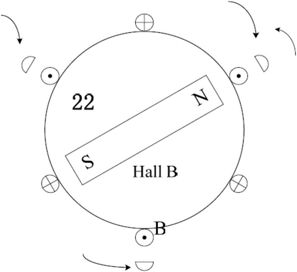
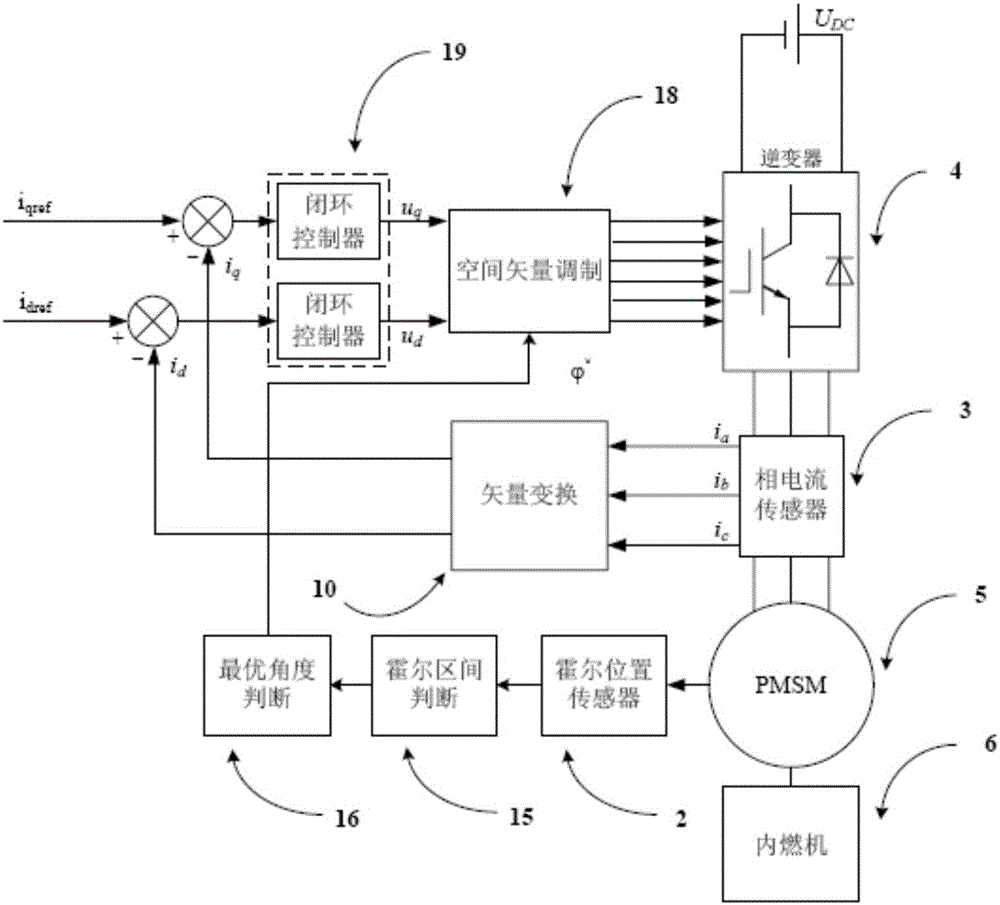
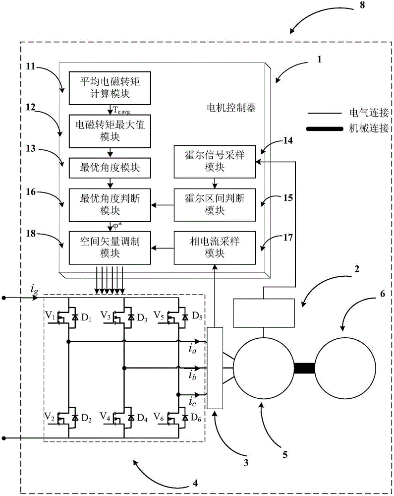
[0035] Combine below Figure 1 to Figure 3 , to further describe the present invention in detail.

[0036] A method for starting a permanent magnet synchronous motor for a range-extending system using a Hall position sensor, figure 1 It is a starting structure diagram of the range-extending system. The range-extending system 8 includes: a motor controller 1, a Hall position sensor 2, a phase current sensor 3, a three-phase inverter bridge 4, a permanent magnet synchronous motor 5, and an internal combustion engine 6. in:

[0037] The motor controller 1 is responsible for sampling various sensor signals, such as the three-way digital signal sampled from the Hall position sensor 2, the three-phase phase current signal sampled from the phase current sensor 3, and the motor controller 1 outputs PWM signals to control the three-phase Inverter bridge 4, its hardware carrier can be one or several combinations in DSP, FPGA, ARM, PLC;

[0038] The internal combustion engine 6 and th...


PUM


Abstract

The invention discloses a permanent magnet synchronous motor starting method for a mileage increasing system provided with a hall position sensor, which belongs to the field of motor control. Due to three ways of digital signals outputted by a three-way switch hall sensor through filtering, six accurate rotor position signals can be determined, 360-DEG electric angle space is uniformly divided into six hall intervals, the maximum value of an average electromagnetic torque is solved through a trigonometric function extremum seeking method, a corresponding optimal angle phi<*> in each hall interval is acquired, the corresponding optimal angle phi<*> serves as an angle signal modulated by a space vector to be inputted, the output PWM signal modulated by the space vector controls a three-phase inverter bridge to generate a stator current vector IS, an electromagnetic torque is generated in a stator winding of the permanent magnet synchronous motor, the permanent magnet synchronous motor is dragged to start, an internal combustion engine is further dragged to start, the mileage increasing system permanent magnet synchronous motor starting function is realized, the maximum electromagnetic torque output is ensured, real-time estimation does not need to be carried out on a rotor position, the algorithm is simple and effective, and the space and the cost are saved.

Description

technical field [0001] The invention relates to a starting method of a permanent magnet synchronous motor for a range-extending system using a Hall position sensor, especially used when starting an internal combustion engine in the range-extending system, and belongs to the field of motor control. Background technique [0002] Extended-range electric vehicles can adapt to the needs of long and short driving distances, require a small battery capacity, and do not require deep discharge. Compared with other new energy vehicles, they have certain advantages. The extended-range electric vehicle is also named because the vehicle is equipped with a range-extended system. The purpose of the extended-range system is to further increase the cruising range of pure electric vehicles, reduce the number of deep discharges of the battery, and improve the life of the battery. [0003] During the starting process of the range-extending system, the starter motor is required to quickly drag t...

Claims


Application Information

Patent Timeline
Patent Type & Authority Applications(China)
IPC IPC(8): H02P21/34
Inventor 许家群戴佳奇
Owner BEIJING UNIV OF TECH
Learn More