Abnormality diagnosis apparatus for exhaust purification system

a technology of abnormal diagnosis and exhaust purification system, which is applied in the direction of human health protection, separation processes, instruments, etc., can solve the problems of degrading exhaust emission, degrading exhaust emission, and defective injection valves, and achieves the effect of easy detection

Active Publication Date: 2010-05-13
TOYOTA JIDOSHA KK
View PDF3 Cites 34 Cited by
  • Summary
  • Abstract
  • Description
  • Claims
  • Application Information

AI Technical Summary

Benefits of technology

[0007]The present invention has been made in view of the above-described circumstances. An object of the present invention is to provide an abnormality diagnosis apparatus for an exhaust purification system which enables abnormalities in a urea addition system in a urea SCR system to be suitably and easily detected.
[0014]During the fuel cut, exhaust gas containing no NOx (the gas is substantially air) passes through the NOx catalyst. In this condition, the addition of the predetermined amount of urea aqueous solution allows all of the urea aqueous solution to be hydrolyzed into ammonia in the NOx catalyst. The ammonia flows out from the NOx catalyst and is then sensed by the sensor. That is, with NOx removed from the exhaust gas, the addition of the predetermined amount of urea aqueous solution results in a sensor output corresponding to the amount of the urea aqueous solution, with reactive consumption of urea with NOx prevented. This output condition is compared with a previously experimentally determined normal output condition. This enables determination of whether or not an appropriate amount of urea aqueous solution of an appropriate quality has been added. Consequently, an abnormality in at least one of the urea addition device and the urea aqueous solution can be suitably detected.
[0020]The abnormality diagnosis apparatus can detect abnormalities in the urea addition system as a whole but has difficulty distinguishably identifying an abnormality in the urea addition device and an abnormality in the urea aqueous solution, that is, an abnormality in the addition amount of the urea aqueous solution and an abnormality in the quality of the urea aqueous solution. Thus, the provision of the another abnormality detection device detecting an abnormality only in the urea addition device allows an abnormality in the urea aqueous solution to be determined when no abnormality is detected in the urea addition device and when the output condition of the sensor is within the predetermined abnormality range. Thus, the different abnormalities can be distinguished from each other, thus further improving diagnosis accuracy.
[0023]The present invention exerts an excellent effect of allowing abnormalities in the urea addition system of the urea SCR system to be suitably and easily detected.

Problems solved by technology

In an exhaust purification system using the NOx catalyst of selective reduction type, if the urea aqueous solution fails to be appropriately added to the NOx catalyst, exhaust emission may be degraded.
Abnormalities in the urea addition system which may degrade the exhaust emission include an addition amount abnormality in which the urea addition amount deviates from a preset value and a quality abnormality in which the properties (particularly the concentration) of the urea aqueous solution deviate from preset ones.
The former may occur when an abnormality occurs in the urea addition device itself, for example, a urea injection valve becomes defective.
Furthermore, in connection with the abnormality in the quality of the urea aqueous solution, such a urea aqueous solution concentration detection device as described in Japanese Patent Application Laid-Open No. 2005-83223 is generally expensive and thus unsuitable for being mounted in a vehicle.
This complicates the configuration of the apparatus and increases costs.

Method used


Image

  • Abnormality diagnosis apparatus for exhaust purification system
  • Abnormality diagnosis apparatus for exhaust purification system
  • Abnormality diagnosis apparatus for exhaust purification system

Examples


Embodiment Construction

[0030]The best mode for carrying out the present invention will be described with reference to the accompanying drawings.

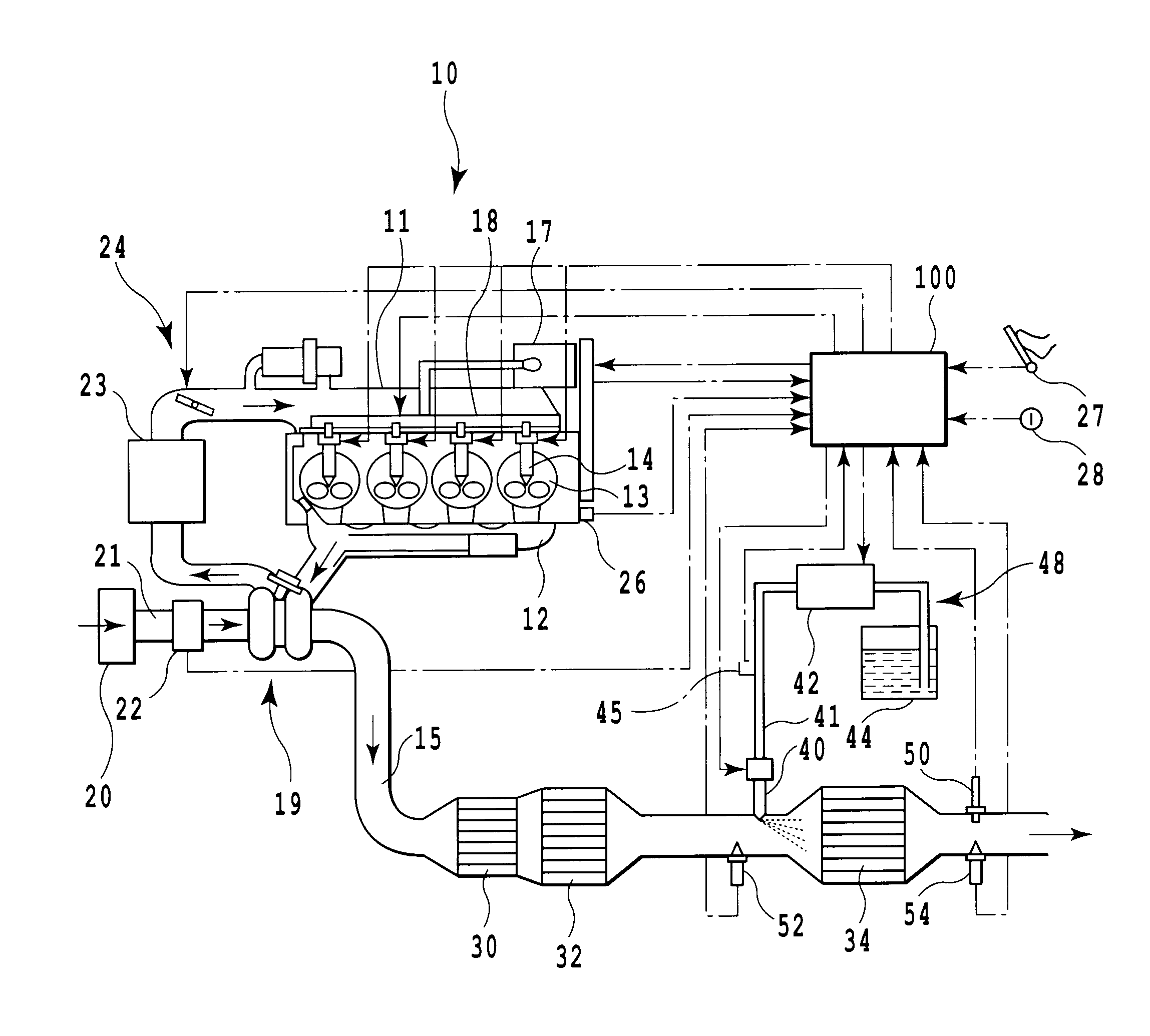
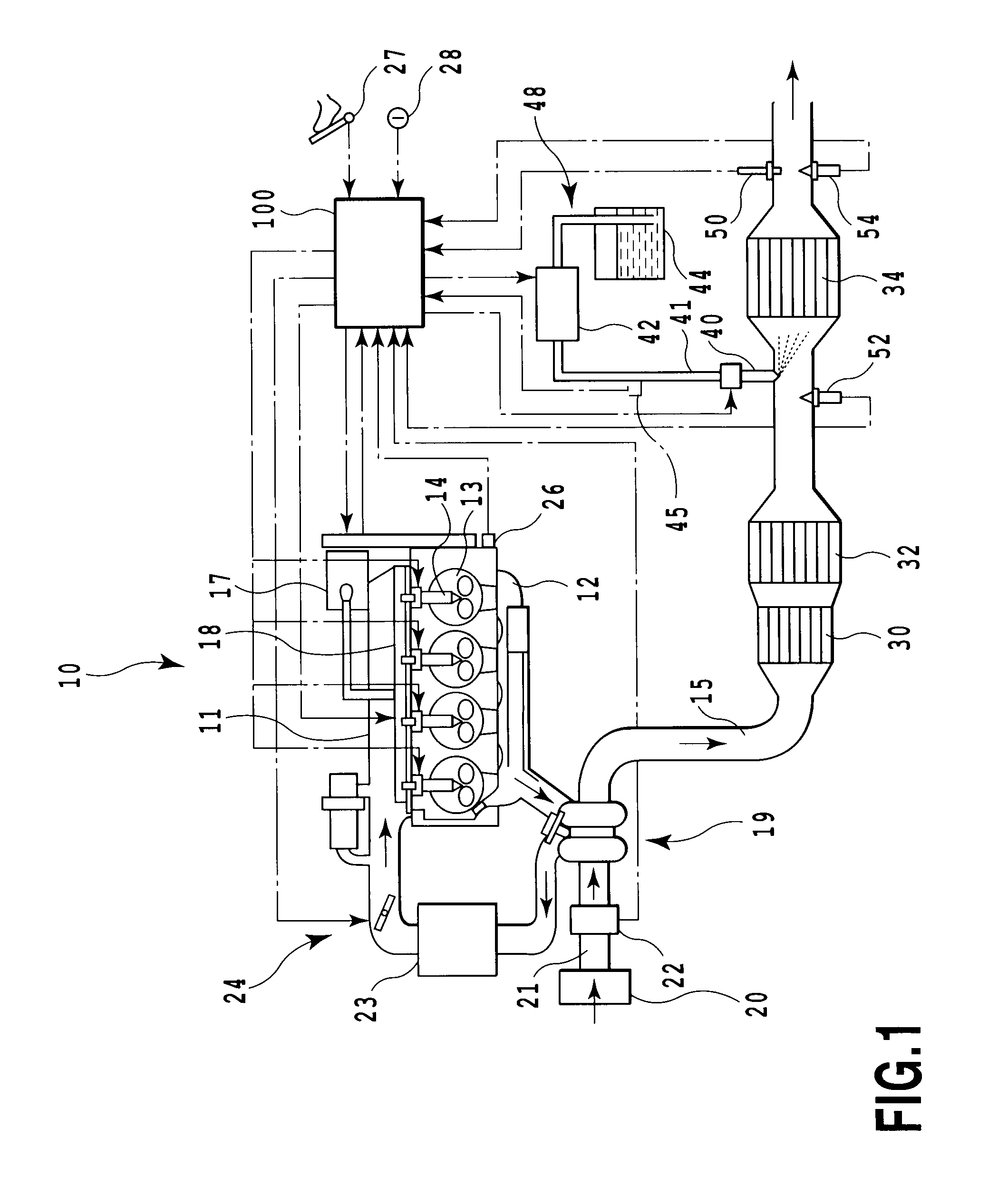
[0031]FIG. 1 is a schematic system diagram of an internal combustion engine according to an embodiment of the present invention. In the figure, reference numeral 10 denotes a compression ignition type internal combustion engine, that is, a diesel engine, and reference 11 denotes an intake manifold that is in communication with an intake port. Reference numeral 12 denotes an exhaust manifold that is in communication with an exhaust port, and reference numeral 13 denotes a combustion chamber. In the present embodiment, fuel fed from a fuel tank (not shown in the drawings) to a high pressure pump 17 is fed to a common rail 18 under pressure by the high pressure pump 17. The fuel is then stored under a high pressure. The high-pressure fuel in the common rail 18 is injected and fed from an injector 14 directly into the combustion chamber 13. Exhaust gas from the engine...


PUM

PropertyMeasurementUnit
temperatureaaaaaaaaaa
timeaaaaaaaaaa

Abstract

In an exhaust purification system having a urea addition device adding a urea aqueous solution to an NOx catalyst of selective reduction type provided in an exhaust passage in an internal combustion engine, a sensor detecting an ammonia concentration is provided at the downstream side of the NOx catalyst. During fuel cut, a predetermined amount of urea aqueous solution is added. Then, based on a sensor output obtained at this time, an abnormality in at least one of the urea addition device and the urea aqueous solution is detected. The addition of the urea aqueous solution during the fuel cut prevents reactive consumption between urea and NOx. The sensor output corresponding to the amount of the urea aqueous solution is obtained. This output condition is compared with a normal one to allow determination of whether or not an appropriate amount of urea aqueous solution of appropriate quality has been added.

Description

TECHNICAL FIELD[0001]The present invention relates to an abnormality diagnosis apparatus for an exhaust purification system, and in particular, to an abnormality diagnosis apparatus for an exhaust purification system that adds a urea aqueous solution to an NOx catalyst of selective reduction type to reduce and remove NOx in exhaust gas (what is called a urea SCR system).BACKGROUND ART[0002]In general, as an exhaust purification apparatus located in an exhaust system for an internal combustion engine such as a diesel engine, an NOx catalyst is known which is used to purify NOx (nitrogen oxide) contained in exhaust gas. Various types of NOx catalysts are known. Among these NOx catalysts, an NOx catalyst of selective reduction type is well known to which a reducing agent is added to continuously reduce and remove NOx. As a reducing agent, urea is commonly used in the form of a water solution. A urea aqueous solution is injected and fed into exhaust gas present on the upstream side of t...

Claims


Application Information

Patent Timeline
Patent Type & Authority Applications(United States)
IPC IPC(8): F01N11/00G01M15/10
CPCB01D53/30Y02A50/2344B01D53/9477B01D53/9495B01D2251/2067B01D2255/1021F01N3/035F01N3/08F01N3/2066F01N11/00F01N2550/05F01N2560/00F01N2560/021F01N2560/026F01N2560/06F01N2560/14F01N2570/14F01N2610/02F01N2900/1808Y02T10/47Y02T10/24B01D53/9409Y02A50/20Y02T10/12Y02T10/40F01N3/20B01D53/94
Inventor SAWADA, HIROSHISHIBATA, DAISUKE
Owner TOYOTA JIDOSHA KK
Why Eureka
Try Eureka