
Process and a plant for the production of metal strip

Active Publication Date: 2010-05-13
DANIELI & C OFF MEC SPA
View PDF12 Cites 12 Cited by
  • Summary
  • Abstract
  • Description
  • Claims
  • Application Information

AI Technical Summary

Benefits of technology

[0012]It is the primary object of the present invention to provide an ultracompact plant and a related endless process for the production of hot rolled steel strip starting from thin slabs obtained by continuous casting at high rates.
[0013]It is another object of the present invention to obtain a hot rolled strip having a thickness variable in the range from 0.8 to 12 mm, having an inner structure with fine grains which are so uniformly distributed as to already display the typical features of a cold rolled material and thus have a high quality and no defects.
[0014]It is a further object of the invention to provide a plant capable to directly produce in endless mode hot rolled coils from liquid steel, with a productivity in the range between 500.000 and 1.500.000 tons / year which reduces investment and running costs if compared to a traditional plant to produce the same thicknesses of strip.

Problems solved by technology

A first problem occurring in production lines made in this manner is related to the extensive overall length of the line, that not only affects the investment costs, but also the production energy costs and the maintenance costs.
Another problem with the known plants concerns the discontinuity of the production process which implies a interruption of feeding to the rolling mill and the impossibility to roll without interruption, that is in the so-called “endless” mode, with subsequent negative repercussions on the energy consumptions and on the environmental impact.

Method used


Image

  • Process and a plant for the production of metal strip
  • Process and a plant for the production of metal strip
  • Process and a plant for the production of metal strip

Examples


Embodiment Construction

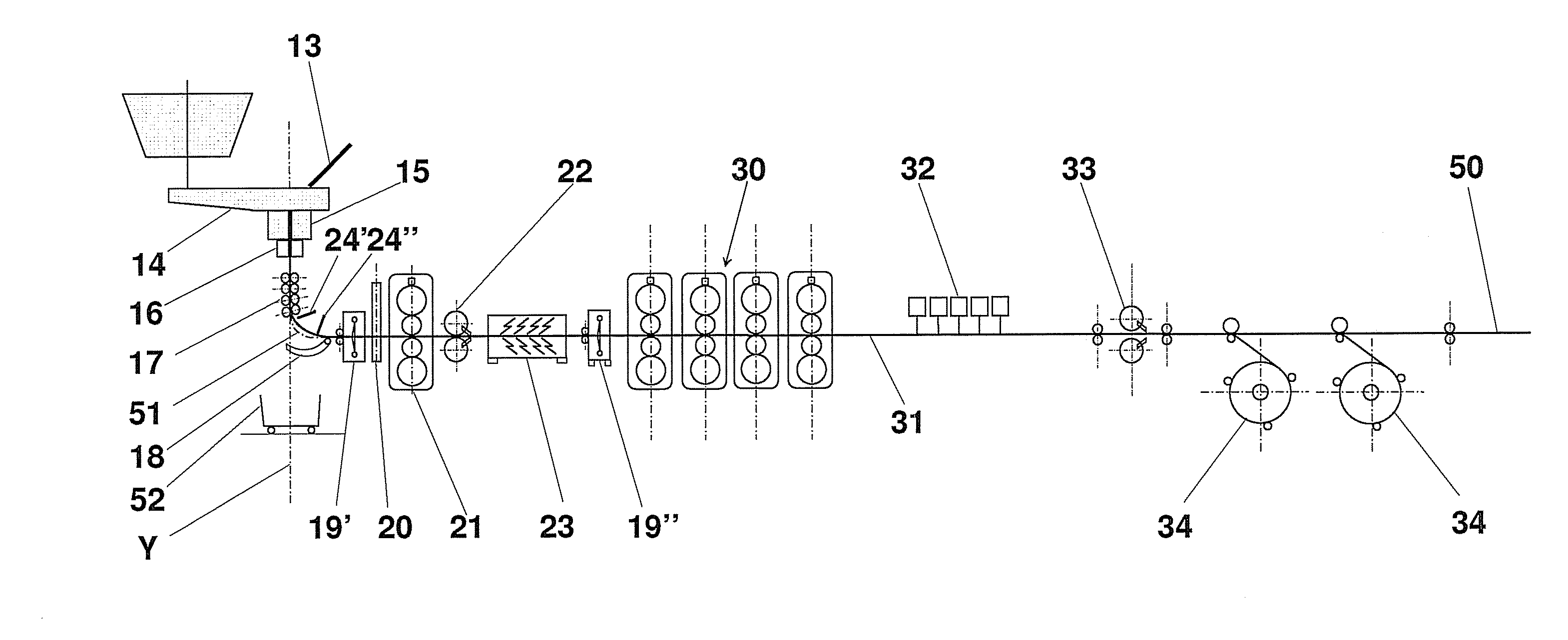
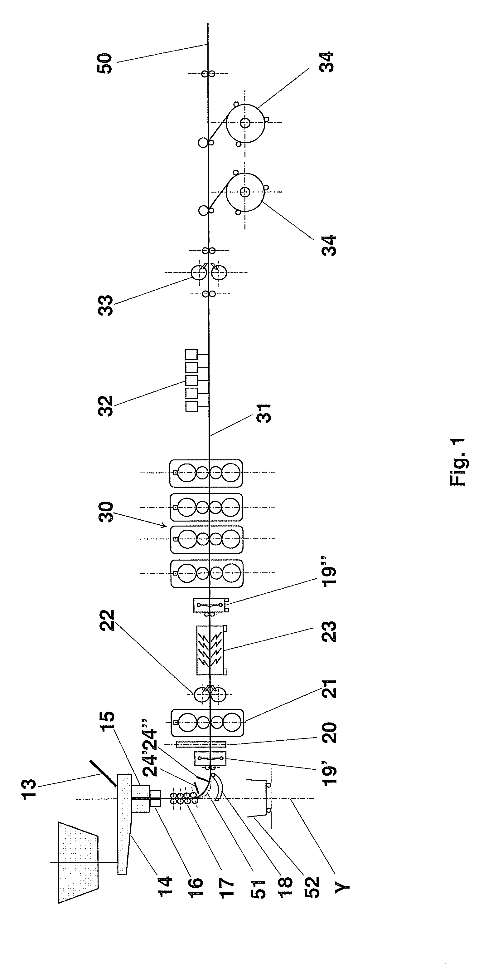
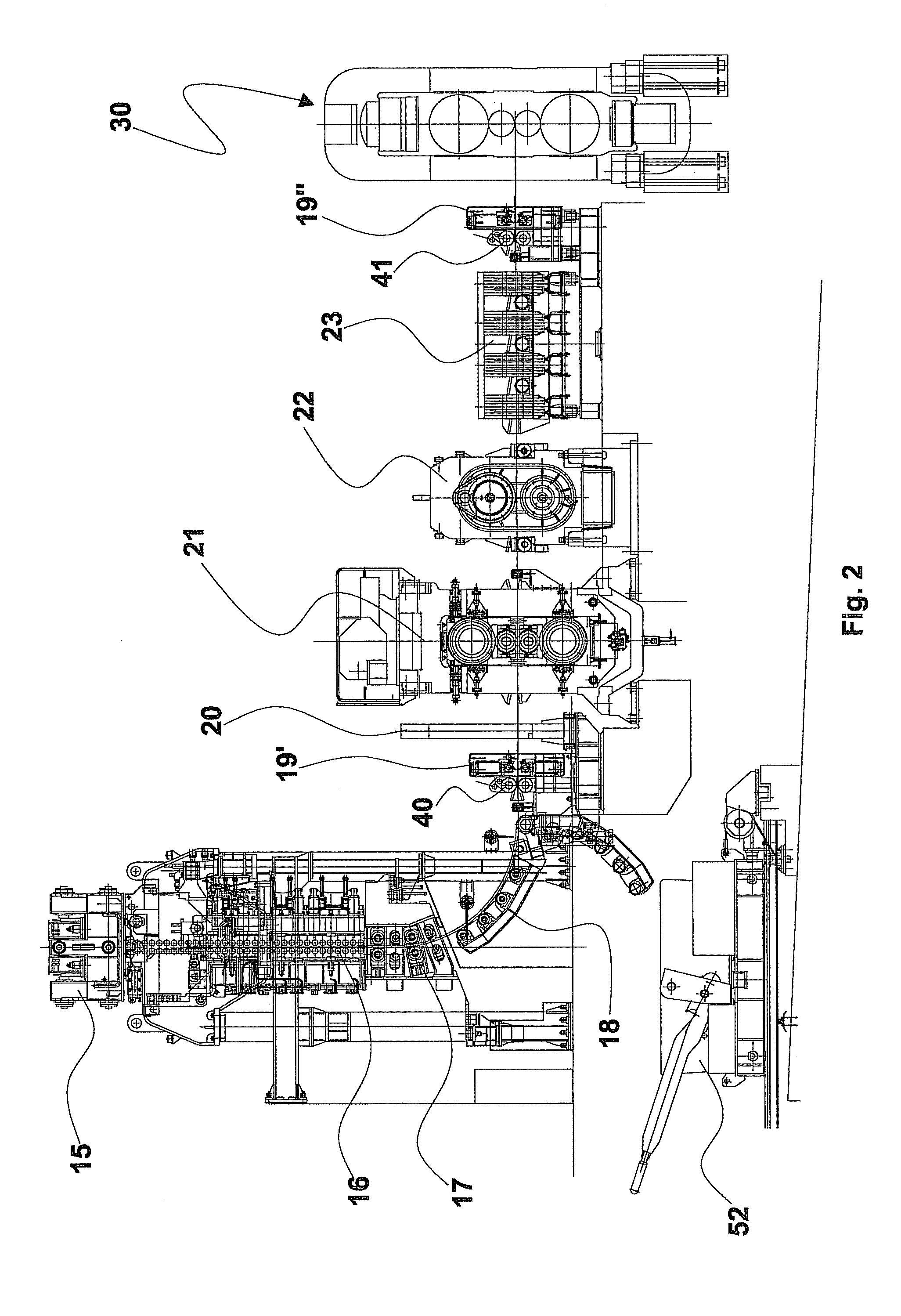
[0058]With reference to the FIGS. 1 and 2 a plant for the production of metal strips is shown, comprising:[0059]an ingot mould 15 which includes a crystalliser for the production of thin slabs with a liquid core,[0060]a liquid core pre-rolling device, or “soft reduction” device 16, placed near the outlet section of the ingot mould and producing a completely solidified cast product,[0061]a first pinch roll 17 of the cast product, adapted to convey the cast product and which may also carry out a slight reduction of the thickness;[0062]cutting means 24′, 24″, such as for instance one or more oxygen cutting devices, to carry out the cutting of the slab in case of emergency, such as for instance a cobble in the rolling mill or a breakout or a sticking in the casting line; the oxygen cutting devices are completely automated and, being controlled by appropriate robots, carry out the cutting of the slab in a direction transversal to the casting direction while the same is moved forward to c...


PUM

PropertyMeasurementUnit
Temperatureaaaaaaaaaa
Lengthaaaaaaaaaa
Lengthaaaaaaaaaa

Abstract

A process and an ultracompact plant for the endless production of hot rolled steel strip comprising an ingot mould (15) that produces a very thin slab, having narrow sides with thickness in the range between 40 and 55 mm and a central swelling, at a speed in the range between 4 and 16 m / min. Such a slab, which displays a core in which the steel is still liquid, is passed through a vertical pre-rolling device (16) that reduces the thickness of the slab and flattens it. The solidified slab may thus be subjected to a first mild rolling by a conveyor (17) and, by forming a free curve, takes a horizontal position where it is subjected to a first surface descaling, a first rolling, a heating in an inductor (23), a second surface descaling and a series of reductions in a rolling mill (30) formed by at least two stands, by maintaining its temperature along the mill above the recrystallisation point Ar3. Downstream of the rolling mill (30) there are provided a roller runway with cooling showers, a flying shear (33) for cutting to length the strip produced, pinch rolls and at least two spinning wheels (34) for the formation of coils of the hot rolled strip.

Description

FIELD OF THE INVENTION[0001]The present invention relates to a process and a related plant for the endless production of a hot rolled steel strip from thin slabs cast at a high rate.STATE OF THE ART[0002]There are known in the state of the art processes and plants for the production of hot rolled steel strip starting from a classical slab, having a thickness from 150 up to 320 mm, or from a normal thin slab having a thickness of about 60-90 mm.[0003]Such plants comprise at least one ingot mould lowerly associated to a curved roller path, or roller conveyor, adapted to contain and guide the cast slab in the passage from the vertical casting direction to the horizontal rolling direction. Normally, the metallurgic cone, that is the substantially conical central area of the slab in which the steel still remains liquid, extends outside the ingot mould and closes along the curved path, so that the completion of the solidification occurs in the roller runway.[0004]The rollers at the metall...

Claims


Application Information

Patent Timeline
IPC IPC(8): B22D11/20B22D11/00B22D11/14B22D11/126
CPCB21B1/26Y02P70/129B21B13/22B21B39/00B21B39/006B21B45/004B21B45/008B21B45/08B21B2201/10B21B2201/14B21B2201/18B22D11/1206Y10T29/49991Y02P70/127B21B1/463Y02P70/10B21B38/00
Inventor BENEDETTI, GIANPIETROPOLONI, ALFREDOKAPAJ, NUREDIN
Owner DANIELI & C OFF MEC SPA
Learn More