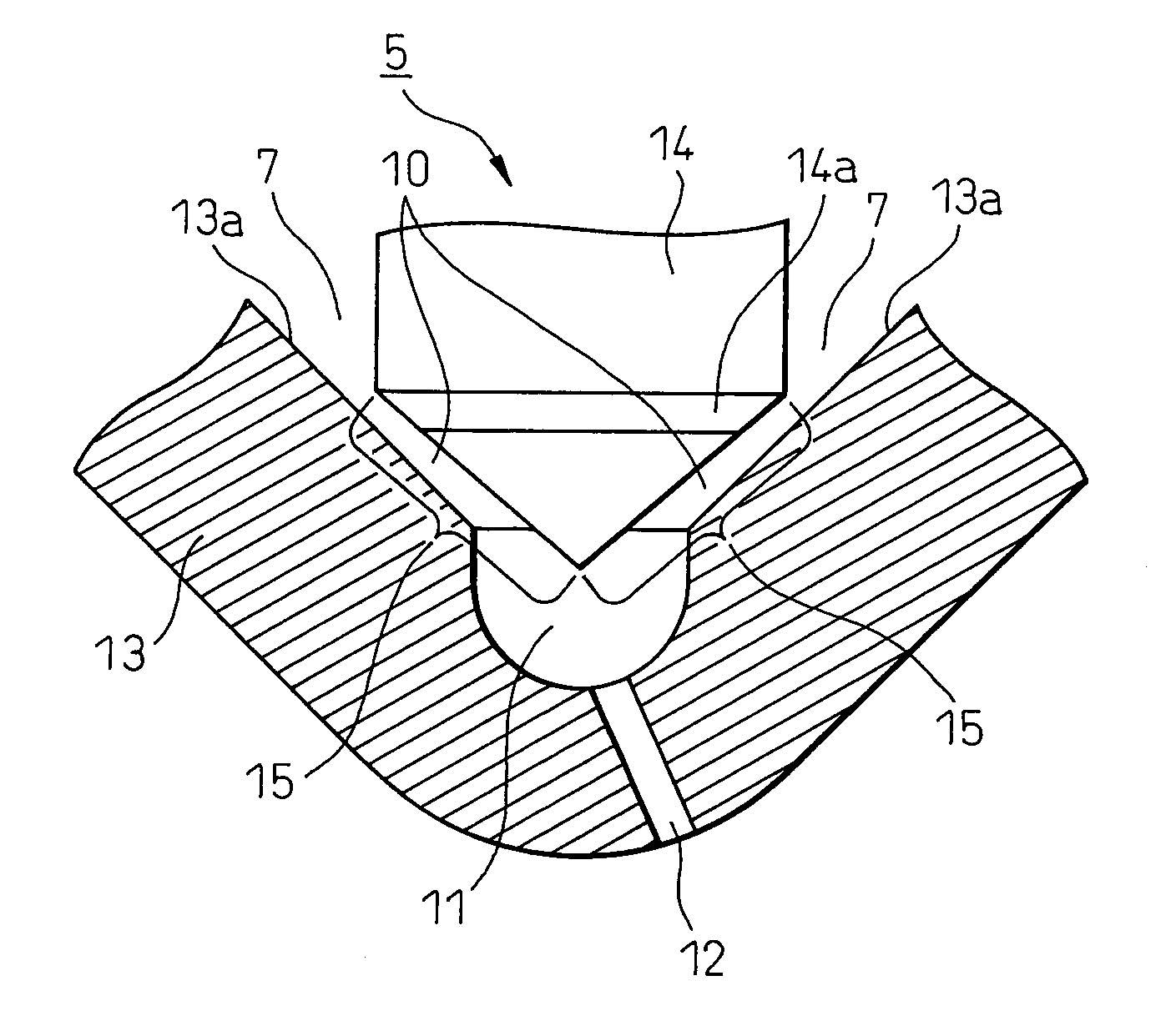
Fuel injector

a fuel injector and fuel technology, applied in the field of fuel injectors, can solve the problems of deteriorating combustion, liable to plug up the injection hole, and the proposed fuel injectors, and achieve the effect of simple configuration and improved durability

Inactive Publication Date: 2010-05-13
TOYOTA JIDOSHA KK
View PDF4 Cites 1 Cited by
  • Summary
  • Abstract
  • Description
  • Claims
  • Application Information

AI Technical Summary

Benefits of technology

[0019]Therefore, the present invention has as its object the elimination of the above problems in the prior art and the provision of a fuel injector inhibiting the adhesion of deposits and simultaneously improving the durability by a simple configuration.
[0026]The inventors newly discovered that by coating an injection hole adjoining a combustion chamber and exposed to a high temperature by a material with a low adsorption and reactivity with oxygen and coating a seal part of a needle relatively separated from the combustion chamber and with a relatively low peak temperature by a material with a high liquid repellency and low oxygen adsorption energy, that is to say, employing selective coatings, it is possible to greatly reduce the deposits and simultaneously secure durability, and thereby completed the present invention.

Problems solved by technology

They cause a drop in the flow and cause fluctuations in the amount of fuel injection and are liable to cause deteriorated combustion.
Further, if deposits further adhere, they are even liable to plug up the injection hole.
However, the above proposed fuel injectors had the following problems.
The fuel injector according to Japanese Patent Publication (A) No. 2003-503637 had an injection hole facing the combustion chamber and exposed to a high temperature, so with a fluororesin, the durability was liable to be insufficient.
If part of the resin coating became damaged and dropped off, deposits were liable to form starting from the dropped off parts.
Further, the fuel injector according to Japanese Patent No. 3156610 had a coating with a low adsorption energy, so if effectively formed, there would be a high effect in inhibiting the formation of deposits, but the coating was carbon-based and was extremely thin, so depending on the surface conditions of the coating, the durability was liable to fall.
These could not be immediately used for practical application.
The fuel injector according to Japanese Patent Publication (A) No. 2001-280224 required provision of an insert at the valve seat of the needle, so there were the defects that the structure became complicated and the production cost rose.

Method used


Image

  • Fuel injector
  • Fuel injector
  • Fuel injector

Examples


examples

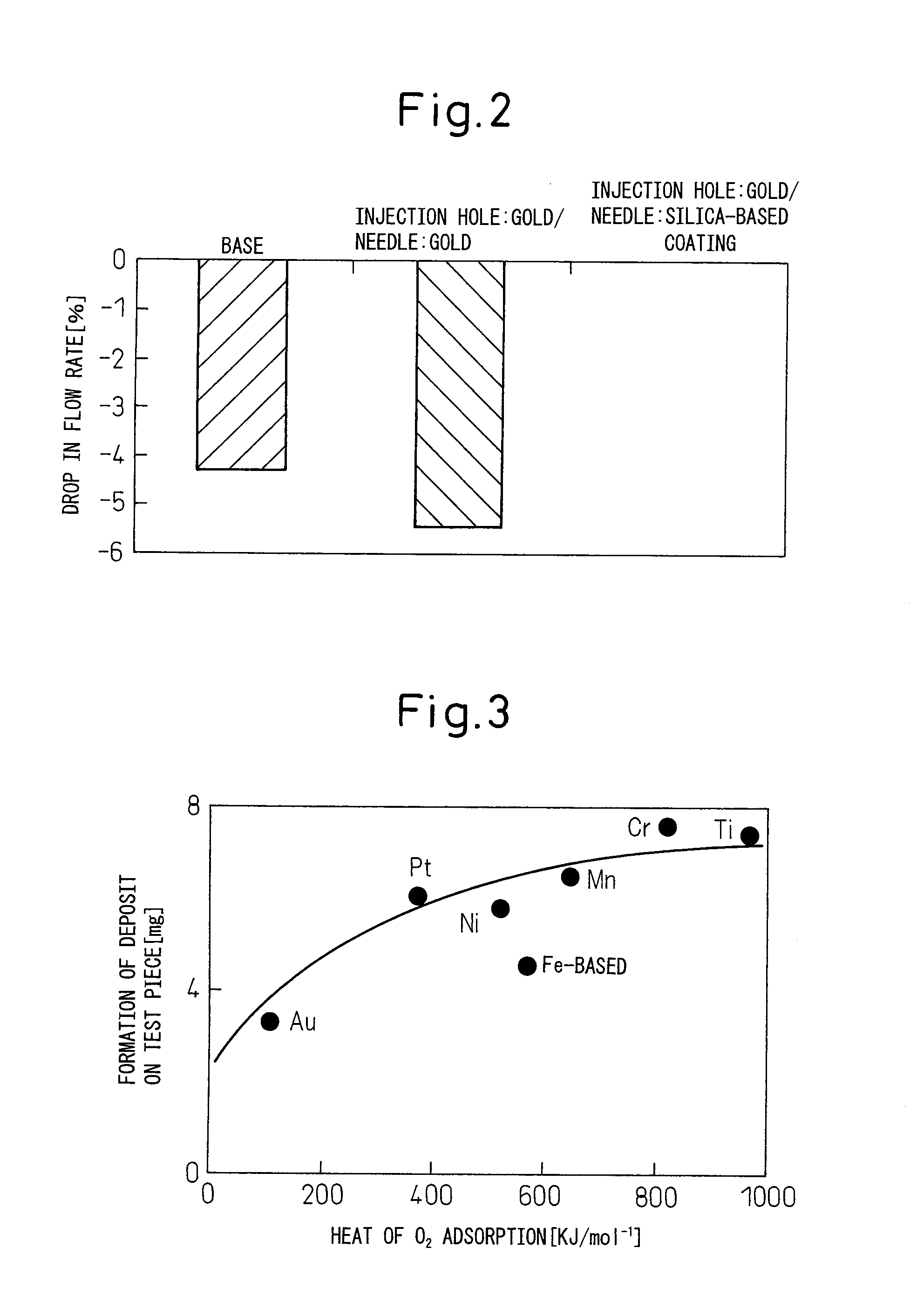
[0047]The selective coatings of the present invention were applied and engine tests conducted. The conditions of the engine tests were as follows:

[0048]

[0049]Engine covered: In-line engine (L4)

[0050]Operating temperature: INJ front end temperature of 150° C.

[0051]Operating time: 40 hours

[0052]Fuel: high octane

[0053]As an invention example, the inner surface of the injection hole was coated with gold, while the needle seal part was given a liquid-repellant coating mainly comprised of SiO2 to which a PTFE resin was added.

[0054]As comparisons, engine tests were run for the case of no coating and the case of coating both the injection hole and needle seal part with the same gold.

[0055]The flow rates of the fuel before and after the tests were measured for the above three cases. The rates of the drop in flow rates after the test compared with the flow rates before the tests were found and evaluated as the drop in the flow rate.

[0056]FIG. 2 summarizes the results of the engine tests as a ...


PUM


Abstract

A fuel injector inhibiting adhesion of deposits and simultaneously improving durability by a simple configuration is provided.A fuel injector havinga valve body provided with a main space receiving fuel and an injection hole anda needle movably supported at the valve body and having a seal part at its front end, in which needle the movement causes the seal part to separate from or contact an inner surface of the valve body and thereby open or close a fuel passage communicating the main space and the injection hole of the valve body,the fuel injector characterized in thatthe injection hole of the valve body is covered by an injection hole coating comprised of a material with a lower adsorption and reactivity with oxygen compared with the material of the valve body itself, andthe seal part of the needle is covered by a seal part coating comprised of a material higher in liquid-repellency compared with the material of the needle itself and not forming a metal surface. Preferably, the material of the injection hole coating is gold and the material of the seal part coating is a silica-based coating material.

Description

TECHNICAL FIELD[0001]The present invention relates to a fuel injector of an in-line injector type internal combustion engine.BACKGROUND ART[0002]In the past, there has been known an in-line injector type internal combustion engine directly injecting fuel into a combustion chamber. Each fuel injector injects fuel into a combustion chamber in accordance with the operating conditions at the necessary timing.[0003]In the combustion chamber, the injected atomized fuel is mixed with the air. The air-fuel mixture formed is ignited by the spark plug and burned.[0004]A fuel injector of an in-line injector type internal combustion engine typically is comprised provided with[0005]a valve body provided with a main space receiving fuel, a sack part serving as a fuel reservoir, and an injection hole arranged in that order and[0006]a needle movably supported at the valve body and having a seal part at its front end, in which needle the movement causes the seal part to separate from or contact an i...

Claims


Application Information

Patent Timeline
Patent Type & Authority Applications(United States)
IPC IPC(8): B05B1/30
CPCF02M61/1806F02M2200/02F02M2200/06F02M2200/9038
Inventor YARINO, MOTONARISUGIMOTO, TOMOJIROMIYAZAKI, SHOUJINITOH, TAKEHIROSHIRASAWA, ATSUSHISATOH, KAZUAKIMATSUMURA, ERIKO
Owner TOYOTA JIDOSHA KK
Why Eureka
Try Eureka