Phase error correction in rotary traveling wave oscillators

a phase error and oscillator technology, applied in the field of electronic oscillators, can solve the problems of complex approaches, limitations of conventional electronic oscillators in their ability to generate signals at these frequencies, etc., and achieve the effect of reducing the detected phase error

Inactive Publication Date: 2010-05-13
PANASONIC CORP
View PDF7 Cites 33 Cited by
  • Summary
  • Abstract
  • Description
  • Claims
  • Application Information

AI Technical Summary

Benefits of technology

[0014]Rotary traveling wave oscillator (RTWO) apparatuses and methods are disclosed. An exemplary method for correcting phase inaccuracy among output phases of a multi-phase RTWO includes detecting a phase error between first and second output phases of the RTWO and controlling the phase velocities of a traveling wave traveling in first and second transmission line segments of a closed-loop transmission line to reduce the detected phase error. According to one aspect of the invention, first and second voltage controlled capacitors having substantially the same capacitance versus voltage characteristics are coupled to the first and second transmission line segments, and first and second control voltages for controlling the first and second vol

Problems solved by technology

Conventional electronic oscillators (e.g., those using lumped element tank circuits) are limited in their ability to generate signals at these frequencies while also maintaining low phase noise.
However those approaches are complex, do not generate square waves, exhibit high levels of jitter, and suffer from large area penalties.
While the RTWO 40 can be used to implement an oscillator having a multi-phase output, the phase accuracy among the multiple phases is not always as accurate as needed or desired, particularly when the R

Method used


Image

  • Phase error correction in rotary traveling wave oscillators
  • Phase error correction in rotary traveling wave oscillators
  • Phase error correction in rotary traveling wave oscillators

Examples


Embodiment Construction

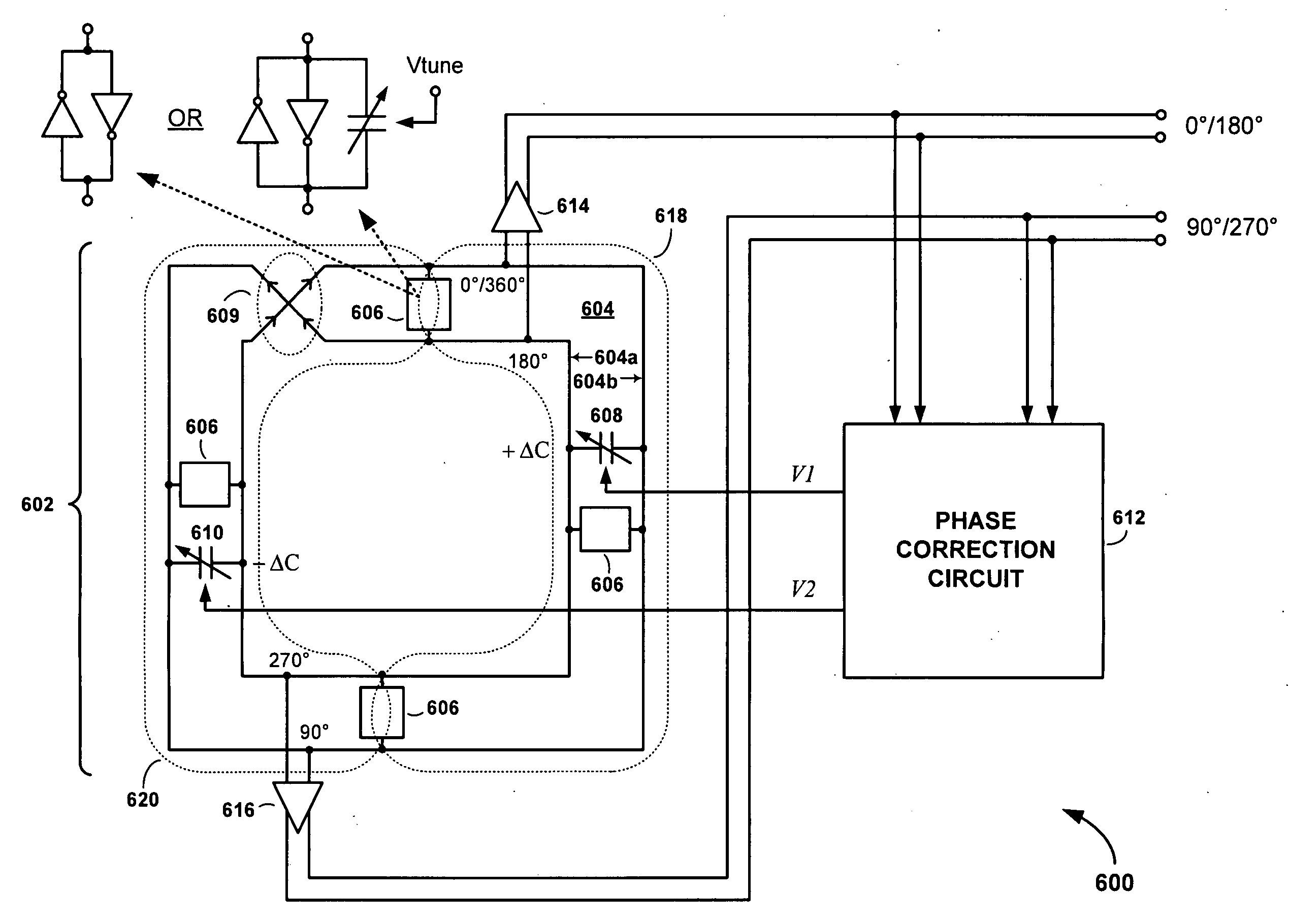
[0030]Referring to FIG. 6, there is shown a drawing of a rotary traveling wave traveling oscillator (RTWO) apparatus 600, according to an embodiment of the present invention. The RTWO apparatus 600 comprises an RTWO 602 including a transmission line 604, a plurality of regenerative circuits 606 and first and second voltage controlled capacitors 608 and 610, and a phase correction circuit 612.

[0031]The transmission line 604 includes a physically and electromagnetically endless conductive signal trace of length l having generally parallel first and second signal trace loops 604a and 604b that merge at a half-twist 609 so that the signal trace forms a Moebius strip. The first and second signal trace loops 604a and 604b are formed on or within a dielectric or semiconductor substrate, and may be disposed either in a single plane using a planar transformer to complete the half-twist 609, or in separate metal layers with a via to close the loop and connect the first signal trace loop 604a ...


PUM


Abstract

An RTWO apparatus includes an N-phase RTWO (N is an integer greater than or equal to two) and a phase correction circuit. The N-phase RTWO includes a closed-loop transmission line formed as a Moebius strip. The closed-loop transmission line includes N transmission line segments, to which N voltage controlled capacitors are coupled. The N transmission line segments provide N output phases. The phase correction circuit operates to detect phase errors between output phases, and, depending on the detected phase errors, generates N control voltages for controlling the capacitances of the N voltage controlled capacitors. Controlling the capacitances of the N voltage controlled capacitors in this coordinated manner reduces the phase errors among the N output phases, thereby providing a phase accurate multi-phase RTWO output.

Description

FIELD OF THE INVENTION[0001]The present invention relates to electronic oscillators. More specifically, the present invention relates to correcting for phase errors in rotary traveling wave oscillators (RTWOs).BACKGROUND OF THE INVENTION[0002]An electronic oscillator is a type of electronic circuit that produces a periodic signal. Electronic oscillators are used in a wide variety of applications including digital sampling circuits and quadrature oscillator generators in communications transceivers, for example.[0003]Many modern electronic systems require electronic oscillators capable of generating signals at microwave and millimeter-wave frequencies. Conventional electronic oscillators (e.g., those using lumped element tank circuits) are limited in their ability to generate signals at these frequencies while also maintaining low phase noise. For this reason, alternative oscillator mechanisms have been sought. One category of electronic oscillators that has gained recent interest as...

Claims


Application Information

Patent Timeline
IPC IPC(8): H03B27/00H03K3/03
CPCH03K3/86H03K3/0315H03B5/1852
Inventor TAKINAMI, KOJIWALSWORTH, RICHARD
Owner PANASONIC CORP
Why Eureka
Try Eureka