Device and method for recording and/or reproducing data onto/from information recording medium by using near-field light and information recording medium

a technology of information recording medium and near-field light, which is applied in the direction of data recording, combination recording, instruments, etc., can solve the problems of near-field light not reaching sil might collide with the surface of the optical disc medium, etc., and achieve the reduction of manufacturing costs of the apparatus, the reduction of the configuration of the optical head, and the reduction of the deterioration of the storage layer and other thin-film layers of the recording medium.

Inactive Publication Date: 2010-05-13
PANASONIC CORP
View PDF15 Cites 2 Cited by
  • Summary
  • Abstract
  • Description
  • Claims
  • Application Information

AI Technical Summary

Benefits of technology

[0043]According to the present invention, a gap servo operation is started at a different location on an information recording medium from any other location where the gap servo operation has ever been started. Thus, it is possible to prevent the laser light emitted at the beginning of a gap servo operation from irradiating the same particular portion over and over again. As a result, deterioration of the storage layer and other thin-film layers of the recording medium can be minimized.
[0044]In addition, even if any particular portion of the information recording medium deteriorated when the gap servo operation was started in the past, the new gap servo operation is started at a different location from that particular deteriorated portion, and therefore, can get done just as intended.
[0045]On top of that, the configuration of the optical head can be simplified, and therefore, the manufacturing cost of the apparatus can be reduced.
[0046]What is more, according to a preferred embodiment of the present invention, locations on an information recording medium where a gap servo operation has been started so far are memorized by a storage section, thus making it possible to determine accurately and easily where the gap servo operation has been started so far.
[0047]Also, according to a preferred embodiment of the present invention, the gap servo operation is started at a different radial location from any other location where the gap servo operation has ever been started. Thus, the location where the gap servo operation is newly started can never be the same as any other location where the gap servo operation has ever been started.
[0048]Furthermore, according to a preferred embodiment of the present invention, the gap servo operation is started at a different circumferential location from any other location where the gap servo operation has ever been started. Thus, the location where the gap servo operation is newly started can never be the same as any other location where the gap servo operation has ever been started.

Problems solved by technology

If the gap between the SIL and the surface of the optical disc medium varied significantly, then the near-field light could fail to reach the surface of the optical disc medium or the SIL might collide against the optical disc medium.
This is because if the movement of the SIL had even a small degree of overshoot or undershoot when it starts to be moved, the SIL might collide against the surface of the optical disc medium.

Method used


Image

  • Device and method for recording and/or reproducing data onto/from information recording medium by using near-field light and information recording medium
  • Device and method for recording and/or reproducing data onto/from information recording medium by using near-field light and information recording medium
  • Device and method for recording and/or reproducing data onto/from information recording medium by using near-field light and information recording medium

Examples


examples

[0149]Hereinafter, specific preferred embodiments of the present invention will be described based on more specific results of experiments.

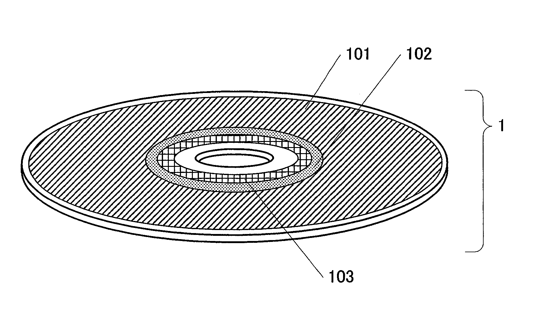
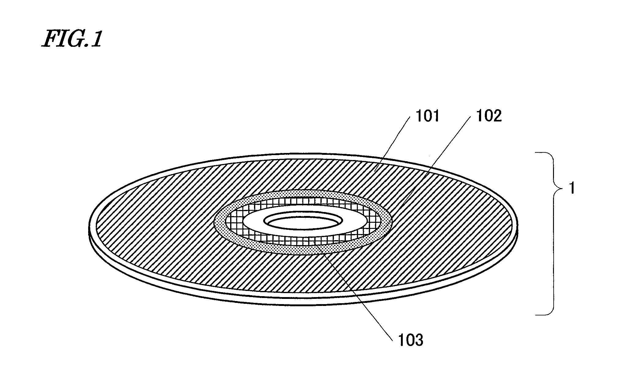
[0150]As the substrate of the optical disc medium 1, a polycarbonate substrate with spiral tracks (or grooves) was used. The grooves were arranged at an interval of 250 nm and had a depth of 20 nm. On this substrate, deposited were a number of thin-film layers, including a phase change storage layer, by sputtering process. These thin-film layers had a four-layer structure consisting of an Ag alloy layer, a ZnS—SiO2 dielectric layer, a GeSbTe phase change storage layer, and a ZnS—SiO2 dielectric layer that had been stacked in this order on the substrate.

[0151]The gap servo area 103 was defined so as to spread from a radial location of 22.0 mm through a radial location of 22.9 mm. The management area 102 was defined so as to spread from a radial location of 23.0 mm through a radial location of 23.9 mm. And the data area 101 was defined so as to spr...


PUM

PropertyMeasurementUnit
depthaaaaaaaaaa
depthaaaaaaaaaa
oscillation wavelengthaaaaaaaaaa

Abstract

An apparatus 100 according to the present invention is designed to read and/or write data from/on an information recording medium 1 using near-field light. The apparatus 100 includes: a light source 3 for emitting laser light; a condensing section 7 for producing the near-field light based on the laser light; a detecting section 22, 23 for detecting the relative positions of the condensing section 7 and the information recording medium 1; and a control section 14 for controlling the position of the condensing section 7. In starting a gap servo operation, the control section 14 controls the position of the condensing section 7 so that the gap servo operation is started at a different location on the information recording medium 1 from any other location where the gap servo operation has ever been started.

Description

TECHNICAL FIELD[0001]The present invention relates to an apparatus and method for reading and / or writing data from / on an information recording medium using near-field light and also relates to an information recording medium for use in such an apparatus and method.BACKGROUND ART[0002]A technique using near-field light has been proposed as a method for reading and writing data from / on an optical disc medium with even higher density.[0003]An optical system including a condenser lens and a solid immersion lens (which will be abbreviated herein as an “SIL”) in combination has recently attracted a lot of attention as a condensing means that produces near-field light. By using such a combination, a numerical aperture (NA) that is higher than that of a condenser lens can be achieved. Generally speaking, the higher the NA of an optical system, the smaller the spot size and the data can be stored with high density.[0004]When a read / write operation is performed on an optical disc medium using...

Claims


Application Information

Patent Timeline
Patent Type & Authority Applications(United States)
IPC IPC(8): G11B11/00G11B7/135
CPCG11B7/00736G11B7/1387G11B7/0945G11B7/08511
Inventor NARUMI, KENJIBIRUKAWA, MASAHIRO
Owner PANASONIC CORP
Why Eureka
Try Eureka