Method for inspecting optical information recording medium, inspection apparatus, optical information recording medium and recording method

a technology of optical information and recording medium, which is applied in the direction of digital signal error detection/correction, instruments, recording signal processing, etc., can solve the problems of inability of optical disc drives to get the focus servo control or tracking servo control done perfectly, the position of information written on the track and the height of storage layer would change quickly, and the level of storage layer change, etc., to achieve the effect of linear velocity and rotational velocity of optical information storage medium, good ser, and low ra

Active Publication Date: 2010-05-13
PANASONIC CORP
View PDF7 Cites 2 Cited by
  • Summary
  • Abstract
  • Description
  • Claims
  • Application Information

AI Technical Summary

Benefits of technology

[0038]According to the present invention, the residual error(s) of a focus error signal and / or a tracking error signal are / is measured with the rotational velocities changed according to the radial location on the optical information storage medium between at least two linear velocities that include a first linear velocity Lv1 and a second linear velocity Lv2 that is higher than the first linear velocity Lv1. By changing the rotational velocities, the linear velocity, and the rotational velocity of the optical information storage medium, can be decreased on an inner area of the storage medium. That is why it is possible to prevent the mechanical factors of the inspecting apparatus itself (such as the vibrations of the inspecting apparatus and the resonance of the actuator) from affecting the residual error(s) of the focus error signal and / or the tracking error signal even in an optical information storage medium from / on which information needs to be read or written at high rates. As a result, the residual errors resulting from the mechanical properties of the given optical information storage medium can be measured precisely.
[0039]Thus, the present invention provides an inspecting method that contributes to sorting out an optical information storage medium of quality that ensures a read signal of quality (i.e., with a good SER) and tracking servo stability. The present invention achieves this object by preventing various types of disturbances such as out-of-plane vibrations, eccentricity, defects and variation in thickness distribution from increasing the residual error components of the tracking error signal so much as to affect the servo stability with a tracking servo failure or the actuator's oscillation while a read / write operation is being performed on the optical information storage medium. The present invention also prevents the residual error components of the focus error signal from increasing so much as to cause the envelope of a write signal to have any missing portion due to the residual error and decreasing the SER of the read signal significantly. The present invention can be used particularly effectively to inspect a write-once or rewritable optical disc on which information can be written at as high a linear velocity as 6× rate for BDs (with a channel clock frequency of 396 MHz).
[0040]On top of that, according to the present invention, at least one of the highest writable linear velocity and radial location information is written on a predetermined area of the optical information storage medium, thereby making it possible to use the same residual error property inspecting apparatus during the manufacturing process of optical information storage media. As a result, the equipment cost can be minimized, the production yield of the media can be increased, and eventually the manufacturing cost of the optical information storage media can be reduced.

Problems solved by technology

The tracking error is sometimes called a “radial tracking error” and the focus error is sometimes called an “axial tracking error”.
Generally speaking, however, if the rotational frequency of a disc were increased, then the locations on the tracks where the information is written and the levels (i.e., heights) of the storage layer would change quickly due to out-of-plane vibrations, eccentricity, defects, variations in thickness distribution and other shape imperfections of the optical disc.
However, there is a certain limit to the response of the servo control.
That is why if the on-track locations or the levels of the storage layer changed at frequencies that are even higher than the quickest possible response of the servo control, then it would be impossible for the optical disc drive to get the focus servo control or the tracking servo control done perfectly.
As a result, the tracking error signal would have an increased residual error (which will be referred to herein as a “residual tracking error”), thus decreasing the stability of the tracking servo.
That is to say, even if the optical disc drive is performing a tracking servo control appropriately enough, the laser beam may still be unable to follow the tracks perfectly to make the level of the tracking error signal not equal to zero, which is what is called a “residual tracking error”.
However, if the spindle motor of such an inspecting apparatus carried out the inspection while rotating at six times as high velocities as normal BDs, then significant residual focus and tracking errors would be detected from mechanical factors of the inspecting apparatus itself, e.g., vibrations and resonance of the actuator.
Then, it would be impossible to precisely measure the residual errors that have been caused due to the mechanical properties of the optical disc (or get the inspection done) just as originally intended.
Nevertheless, if an expensive high-performance inspecting apparatus that would have reduced vibrations or actuator resonance were newly introduced, then investment on equipment should be newly made, thus eventually increasing the manufacturing cost of the media.
This is a problem because 10,000 rpm is the maximum allowable rotational frequency in practice that was determined from safety considerations in view of the rupture limit of plastic that is the substrate material of the disc.
For that reason, if the servo characteristic of the inspecting apparatus should have an even higher gain intersection to cope with the 6× linear velocity for BDs, then the actuator would have a decreased oscillation or phase margin, thus making it virtually impossible to secure servo stability.

Method used


Image

  • Method for inspecting optical information recording medium, inspection apparatus, optical information recording medium and recording method
  • Method for inspecting optical information recording medium, inspection apparatus, optical information recording medium and recording method
  • Method for inspecting optical information recording medium, inspection apparatus, optical information recording medium and recording method

Examples


Embodiment Construction

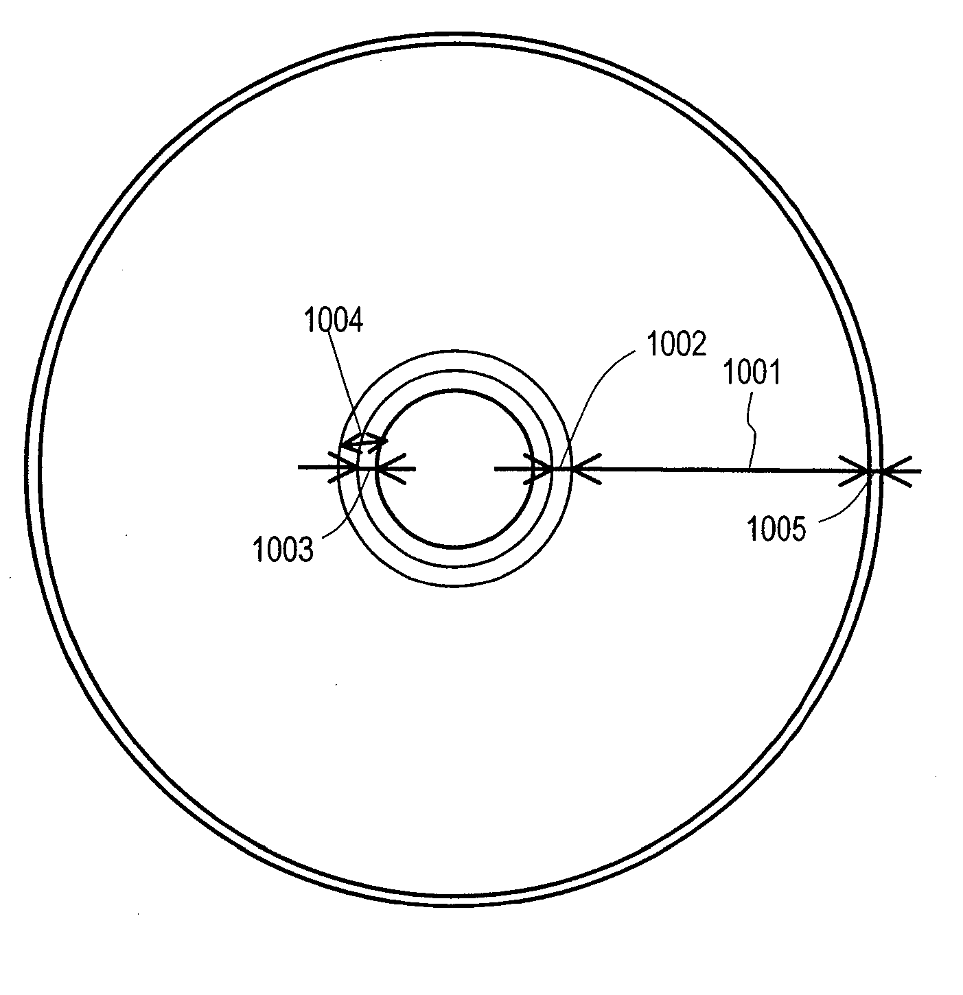
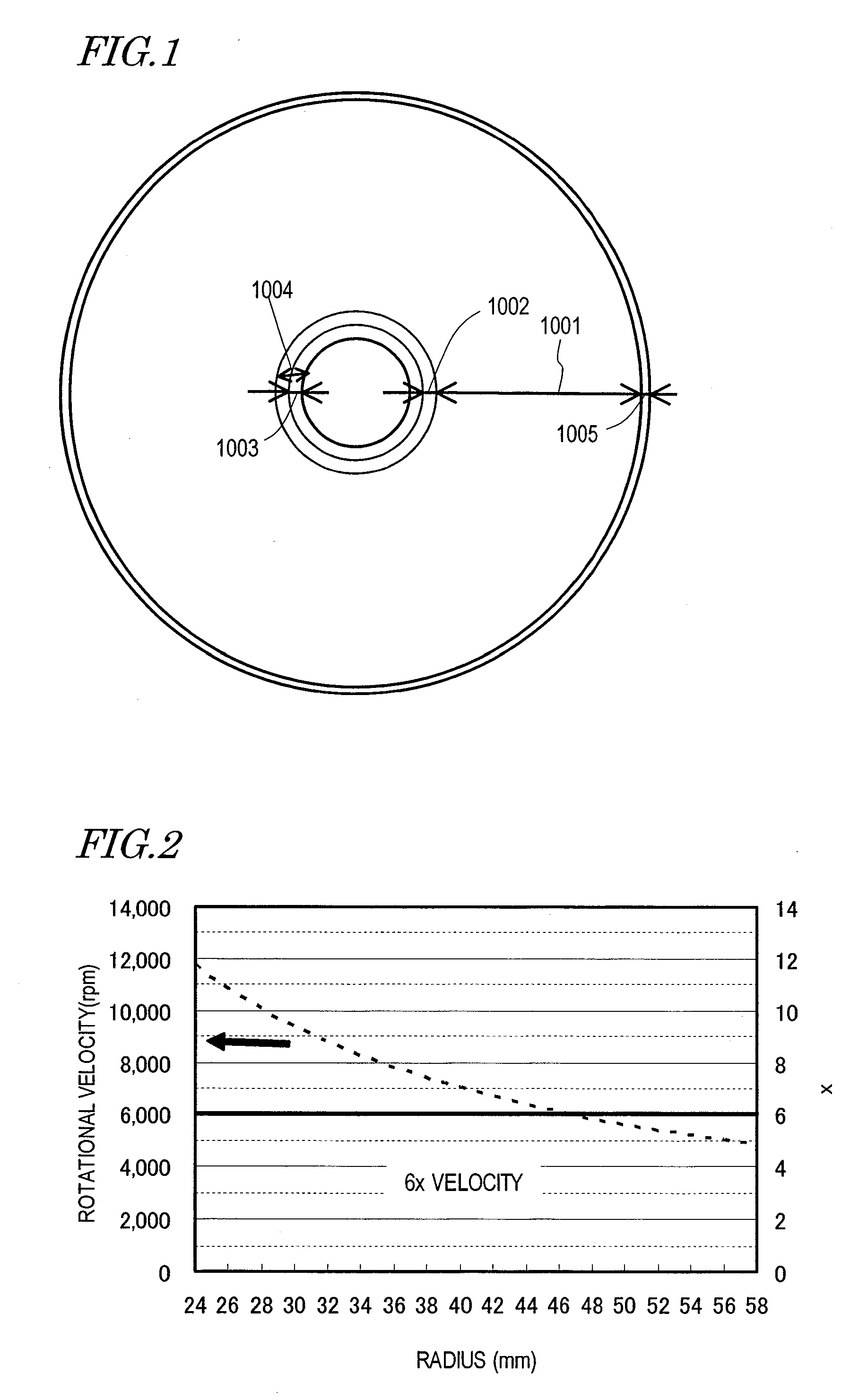
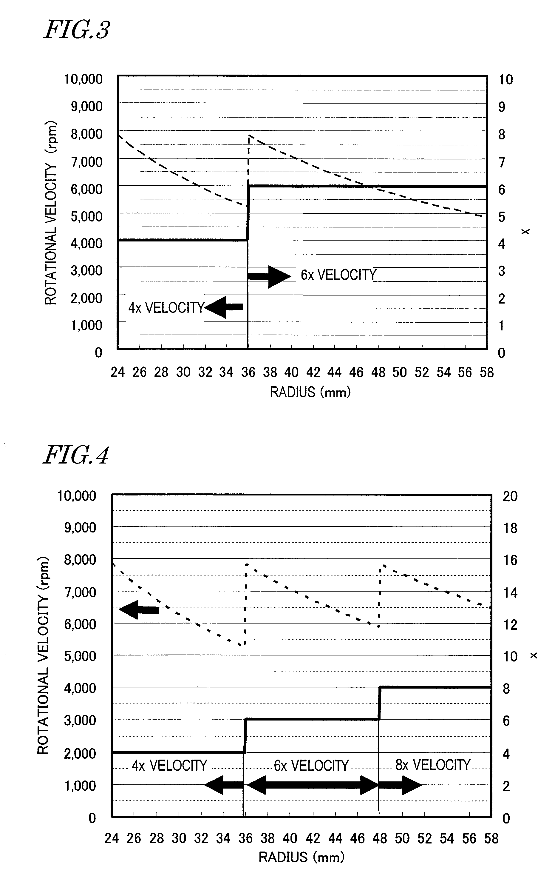
[0056]Hereinafter, preferred embodiments of the present invention will be described as being applied to a BD-R (i.e., write-once Blu-ray Disc, which is one of various types of optical discs) as an exemplary optical information storage medium. However, the present invention is in no way limited to those specific preferred embodiments. Alternatively, an optical information storage medium according to the present invention may also be a BD-RE (i.e., a rewritable Blu-ray Disc) on which information can be rewritten a number of times, a BD-ROM (i.e., a read-only Blu-ray Disc), or an optical disc compliant with any other standard.

[0057]Main optical constants and physical formats for Blu-ray Discs are disclosed in “Blu-ray Disc Reader” (published by Ohmsha, Ltd.) and on White Paper at the website of Blu-ray Association (http: / / www.blu-raydisc.com), for example. Specifically, as for a BD-R, an objective lens for a laser beam with a wavelength of 405 nm and with an NA of 0.85 is used. A BD-R ...


PUM

PropertyMeasurementUnit
linear velocity Lv2aaaaaaaaaa

Abstract

A method for inspecting an optical information storage medium includes the steps of: irradiating the storage medium with a laser beam and rotating the medium by a constant linear velocity control technique by reference to the radial location at which the laser beam forms a spot on the medium; changing the rotational velocities according to the radial location on the medium between at least two linear velocities that include a first linear velocity Lv1 and a second linear velocity Lv2 higher than the first linear velocity Lv1; generating a focus error signal and / or a tracking error signal based on the light reflected from the medium; performing a focus control and / or a tracking control on the laser beam that irradiates the medium based on the focus and / or tracking error signal(s); and passing the branched outputs of control loops for the focus and / or tracking error signal(s) through predetermined types of frequency band-elimination filters for the focus and / or tracking error signal(s) to obtain residual errors of the focus and / or tracking error signal(s) and comparing the residual errors to predetermined reference values.

Description

BACKGROUND OF THE INVENTION[0001]1. Field of the Invention[0002]The present invention relates to a method and apparatus for inspecting an optical information storage medium, an optical information storage medium, and a method of writing information on such a medium. More particularly, the present invention relates to a method and apparatus for inspecting an optical information storage medium on which a read / write operation needs to be performed at high rates and also relates to a method for inspecting such an optical information storage medium for residual focus and tracking errors.[0003]2. Description of the Related Art[0004]An optical information storage medium has a storage layer on which information is written as pits or marks. That information can be read by irradiating the pits or marks with light and by detecting a variation in the intensity of the light reflected. Such an optical information storage medium normally has a disc shape, and therefore, is called an “optical disc”...

Claims


Application Information

Patent Timeline
Patent Type & Authority Applications(United States)
IPC IPC(8): G11B20/18
CPCG11B7/0079G11B7/268G11B2220/2537G11B20/1816G11B20/10046
Inventor NAKAMURA, ATSUSHIFUJIUNE, KENJIHINO, YASUMORI
Owner PANASONIC CORP
Why Eureka
Try Eureka