Optical transmission module and electronic device

a technology of optical transmission and optical signals, applied in the direction of electromagnetic transmission, transmission monitoring, electromagnetic transceivers, etc., can solve the problems of inability to consume power in the stopped state, and inability to suppress power consumption in the standby state of light transmission modules, etc., to achieve accurate transmission and high impedance

Inactive Publication Date: 2010-05-13
ORMON CORP
View PDF10 Cites 26 Cited by
  • Summary
  • Abstract
  • Description
  • Claims
  • Application Information

AI Technical Summary

Benefits of technology

[0041]In this regards, according to the above configuration, the high input impedance circuit is arranged such that the electrical transmission path becomes high impedance when seen from the data signal. The data

Problems solved by technology

Therefore, the power consumption in a case where the light transmission module is in the standby state cannot be suppressed.
Thus, the power in time of standby in the stoppe

Method used


Image

  • Optical transmission module and electronic device
  • Optical transmission module and electronic device
  • Optical transmission module and electronic device

Examples


first embodiment

[0092]One embodiment of the present invention will be described below based on FIG. 3 to FIG. 8.

[0093]In a first embodiment and a second embodiment, to be hereinafter described, a configuration of a foldable portable telephone (hereinafter referred to as portable telephone) including a main body with operation keys, a lid with a display screen, and a hinge for rotatably connecting the main body and the lid, where information (data) transmission between the main body and the lid is carried out through a light transmission module arranged in the hinge will be described by way of example.

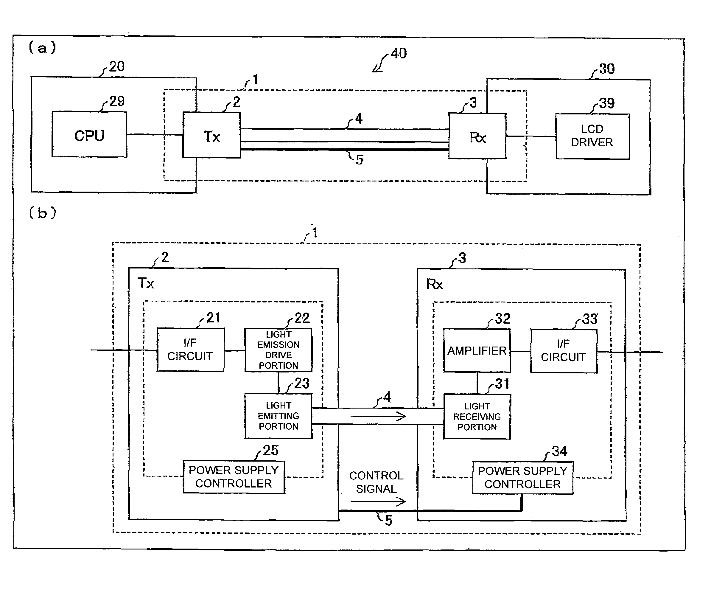
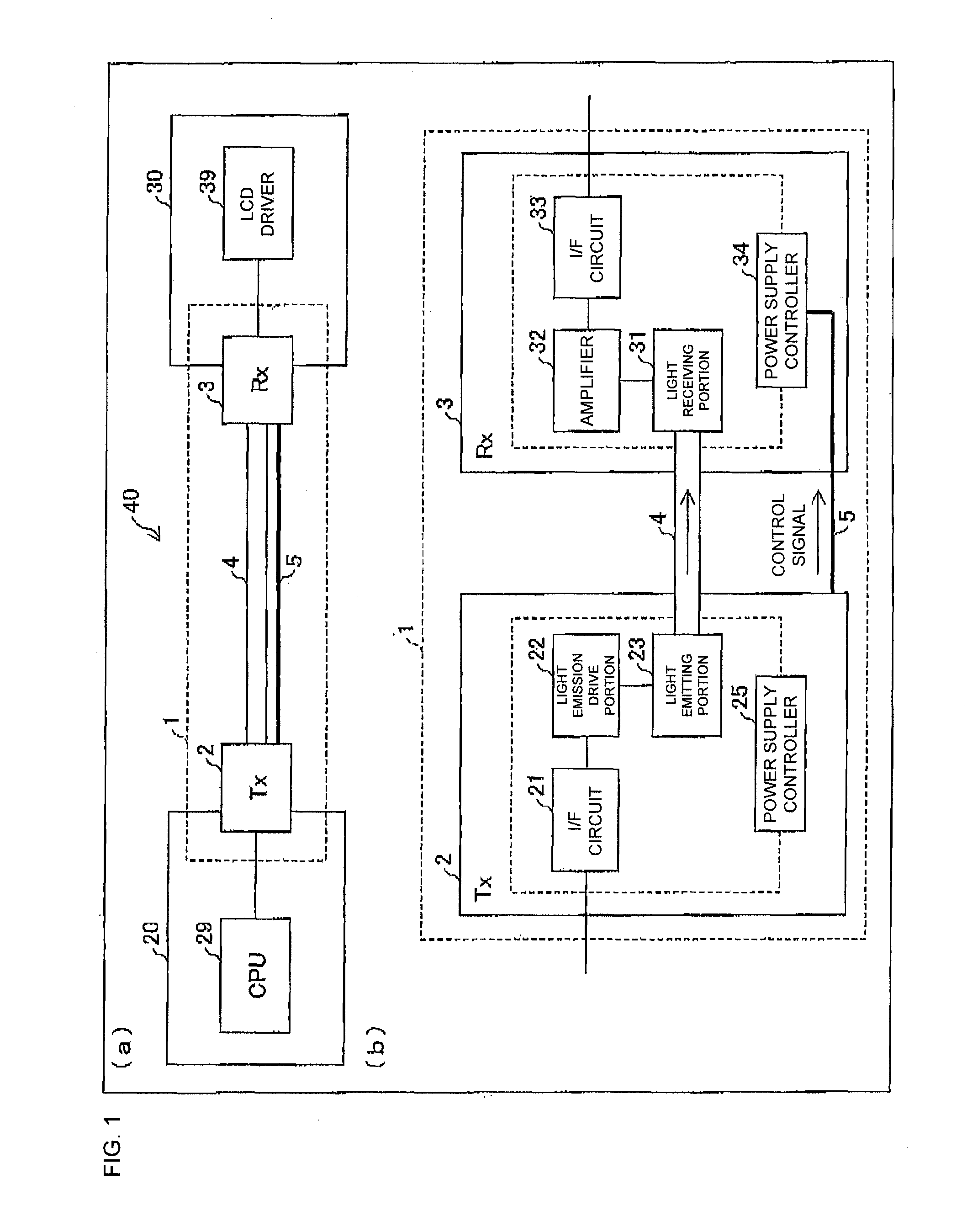
[0094]FIG. 3(a) is a perspective view showing an outer appearance of a portable telephone 40 incorporating a light transmission module 1 of the first embodiment. FIG. 3(b) is a block diagram of a portion applied with the light transmission module 1 in the portable telephone 40 shown in FIG. 3(a). FIG. 3(c) is a perspective plan view of a hinge 41 (portion surrounded with a broken line) in FIG. 3(a).

[00...

second embodiment

[0138]Other embodiments of the present invention will be described below based on FIG. 9 to FIG. 18. For the sake of convenience of the explanation, same reference numerals are denoted for members having the same functions as the members shown in the first embodiment, and the description thereof will be omitted. The terms defined in the first embodiment are used according to such definition in the present embodiment unless otherwise specified.

[0139]FIG. 9(a) is a block diagram of a portion applied with a light transmission module 10 in the portable telephone 40 incorporating the light transmission module 10 of the second embodiment, and FIG. 9(b) is a block diagram showing a schematic configuration of the light transmission module 10.

[0140]In the first embodiment, the signal determination processing portion 24 arranged in the light transmission processing unit 2 determines the presence of the input signal to the light transmission module 1, and outputs the control signal correspondi...

configuration example 1

of Signal Separator

[0162]A configuration example 1 of the signal separator 27 is a configuration of separating the data signal and the control signal based on the value of the frequency of the signal (hereinafter referred to as input signal) input to the light transmission module 10. FIG. 14 is a block diagram showing a schematic configuration of the light transmission module 10 serving as the configuration example 1. As shown in the figure, the signal separator 27 is configured by a high-pass filter (hereinafter referred to as HPF) 271a and a low-pass filter (hereinafter referred to as LPF) 271b. Specifically, the HPF 271a is arranged on the transmission path between the branched portion 5b of the transmission path for data signal transmission and the transmission path for control signal transmission, and the I / F circuit 21 of the light transmission processing unit 2, and the LPF 271b is arranged on the electrical transmission path 5 between the branched portion 5b and the power su...


PUM


Abstract

A light transmission module has a light transmitting unit having a light emitting portion for outputting an optical signal corresponding to a data signal input as an electrical signal, and a first power supply controller for controlling a drive power supply of the light emitting portion, a light transmission path for transmitting the optical signal introduced from the light transmitting unit, a light receiving unit having a light receiving portion for receiving the optical signal output from the light transmission path and outputting an electrical signal corresponding to the optical signal, and a second power supply controller for controlling a drive power supply of the light receiving portion, and at least one electrical transmission path, connecting the light transmitting unit and the light receiving unit, for transmitting a control signal for controlling power supply to the light emitting portion and the light receiving portion to the first power supply controller and the second power supply controller. The first power supply controller and the second power supply controller control the power supply to the light emitting portion and the light receiving portion based on the control signal input via the electrical transmission path.

Description

TECHNICAL FIELD[0001]The present invention relates to light interconnections for connecting circuit boards in an information transmission device such as a portable telephone with an optical signal, and in particular, to a light transmission path module for transmitting optical signals and an electronic device.BACKGROUND ART[0002]In recent years, higher speed in the transmission speed of data is demanded with increase in CPU clock frequency. However, in the conventional electric wiring, crosstalk and electromagnetic radiation become significant with higher speed of the transmission speed, and thus there is a limit to increasing the speed of the transmission speed. A method of connecting the CPU and various types of application circuits with a light transmission path such as a light guide, and transmitting a data signal as an optical signal has been attempted.[0003]The light guide has a double structure of a center core, which is called a core, and a capsule covering the center core, ...

Claims


Application Information

Patent Timeline
IPC IPC(8): H04B10/12H04B10/25H04B10/40H04B10/50H04B10/60H04B10/66H04B10/80
CPCH04B10/808H04B10/801H04B10/25H04B10/50
Inventor UNO, KEISUKEISHIDA, YOSHIHISAENAMI, AKIRAHOSOKAWA, HAYAMI
Owner ORMON CORP
Why Eureka
Try Eureka