Control device and control method for vehicle

a technology for controlling devices and vehicles, applied in the direction of propulsion parts, propulsion using engine-driven generators, process and machine control, etc., can solve the problems of power consumption, power consumption of external charging devices or power storage devices mounted on vehicles, and inability to reduce electric power consumption, so as to reduce power consumption and reduce the charge time of power storage devices.

Inactive Publication Date: 2010-05-13
TOYOTA JIDOSHA KK
View PDF2 Cites 41 Cited by
  • Summary
  • Abstract
  • Description
  • Claims
  • Application Information

AI Technical Summary

Benefits of technology

[0008]An object of the invention is to provide a control device and a control method for a vehicle that can ensure a space for mounting, and further can selectively operate electric devices related to charging of a power storage device during the external charging for achieving reduction in power consumption during the external charging and reduction in charge time of the power storage device.

Problems solved by technology

However, the electric power of the power storage device is limited so that reduction of electric power consumption becomes an important issue in electric devices on the vehicle.
However, the onboard device power saving device disclosed in the foregoing publication suffers from a problem that power consumption of an external charging device or a power storage device mounted on a vehicle cannot be reduced when the power storage device is charged with the external charging device.
Therefore, the electric power may be wasted.
This may result in increase of a charge time.
A power supply device that controls each of powers supplied to the respective electric devices, in which case it may be impossible to ensure a space for mounting the electric devices on the vehicle.
Further, when a plurality of electric devices connected to a communication line corresponding to the same power supply system are configured to operate such that only a part of the electric devices become active, a communication error may occur due to no response of the inactive electric device.
For avoiding the occurrence of the communication error, it is necessary to set an error mask for each electric device so that changes in setting may be complicated.

Method used


Image

  • Control device and control method for vehicle
  • Control device and control method for vehicle
  • Control device and control method for vehicle

Examples


Embodiment Construction

[0041]Embodiments of the invention will now be described with reference to the drawings. In the following description, the same portions bear the same reference numbers and the same names, and achieve the same functions. Therefore, description thereof is not repeated.

[0042]

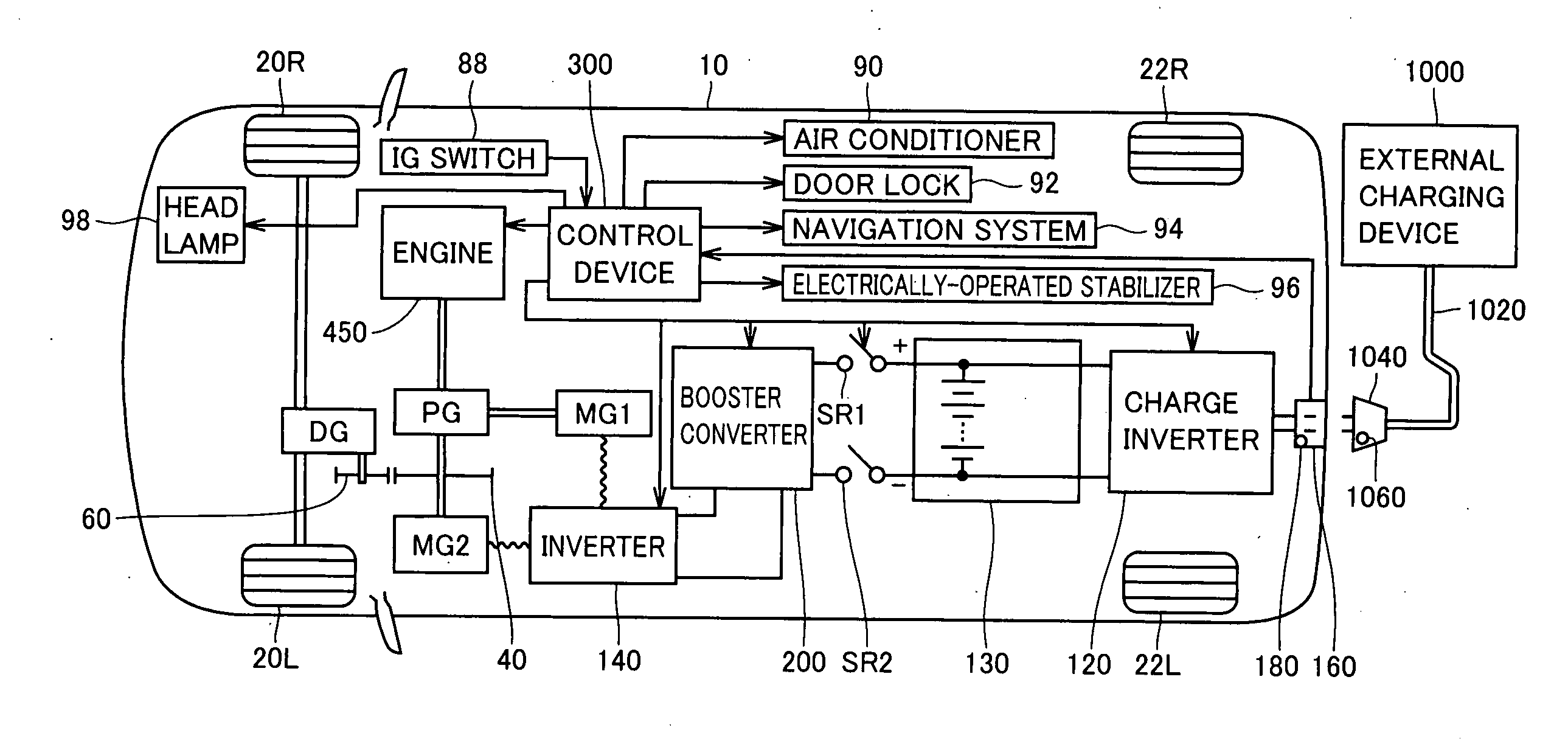
[0043]FIG. 1 is a block diagram showing a structure of a hybrid vehicle 10 according to an embodiment of the invention.

[0044]Referring to FIG. 1, hybrid vehicle 10 includes front wheels 20R and 20L, rear wheels 22R and 22L, an engine 450, a planetary gear PG, a differential gear DG, and gears 40 and 60.

[0045]Hybrid vehicle 10 further includes a battery 130, a booster converter 200 boosting a DC power supplied from battery 130 and an inverter 140 transferring the DC power to or from booster converter 200.

[0046]Hybrid vehicle 10 further includes a motor generator MG1 that receives a drive power of engine 450 via planetary gear PG to generate an electric power, and a motor generator MG2 having a rotation axis connect...


PUM


Abstract

A control device has a coupling determination sensor for detecting external connection of a charge table. When the connection of the charge cable is detected according to a signal from the sensor, the control device activates an electric device connected to a communication line of a charge-time-dedicated power supply system. Since the control device of the invention can activate only the electric device related to the charging while keeping electric devices not related to the charging at rest, and therefore prevents wasteful electric power consumption.

Description

TECHNICAL FIELD[0001]The invention relates to a control device for a vehicle equipped with a power storage device and using at least a rotating electric machine as a drive source, and particularly to a technique that selectively activates an electric device related to charging when an external charging device charges a power storage device.BACKGROUND ART[0002]In recent years, attention has been given to hybrid vehicles and electric vehicles against the background of environmental issues. These vehicles are equipped with a power storage device supplying an electric power to an electric drive motor. However, the electric power of the power storage device is limited so that reduction of electric power consumption becomes an important issue in electric devices on the vehicle.[0003]In view of the above issue, Japanese Patent Laying-Open No. 2002-125301 has disclosed an onboard device power saving device for an onboard device of a vehicle that reduces a quantity of electric power consumed...

Claims


Application Information

Patent Timeline
Patent Type & Authority Applications(United States)
IPC IPC(8): B60L11/18
CPCB60K1/02Y02T90/121B60K6/445B60L11/123B60L11/14B60L11/1811B60L11/1824B60L2240/80B60W10/08B60W10/26B60W20/00H01M10/052H01M10/30H01M10/345H01M10/44H01M10/46H02J7/1438Y02T10/6217Y02T10/6239Y02T10/6269Y02T10/7005Y02T10/7011Y02T10/7077Y02T10/92Y02T90/12Y02T90/127Y02T90/14Y02T90/16B60K6/365Y02T10/7072B60L50/61B60L50/16B60L53/20B60L53/30B60L53/67Y02E60/10Y02T10/62Y02T10/70B60W20/10
Inventor ISHII, KENICHIKOMATSU, MASAYUKIKATSUDA, TOSHIHIROOKI, RYOUJIISHIKAWA, TETSUHIROOHBAYASHI, KAZUYOSHISAWADA, HIROKI
Owner TOYOTA JIDOSHA KK
Why Eureka
Try Eureka