Method of controlling the operation of a selective catalytic reduction plant

a selective catalytic reduction and operation method technology, applied in the direction of exhaust treatment electric control, separation process, lighting and heating apparatus, etc., can solve the problem of system response time to load change very slow, and achieve the effect of quick variations in the amount of nox in the process

Active Publication Date: 2010-05-20
GENERAL ELECTRIC TECH GMBH
View PDF4 Cites 23 Cited by
  • Summary
  • Abstract
  • Description
  • Claims
  • Application Information

AI Technical Summary

Benefits of technology

[0007]An object of the present invention is to provide a method of controlling the supply of a reducing agent, such as ammonia or urea, to an SCR-reactor, which method is capable of handling quick variations in the amount of NOx in the process gases.

Problems solved by technology

EP 0 604 236 B1 notes that such a system has a very slow response time to load changes.

Method used


Image

  • Method of controlling the operation of a selective catalytic reduction plant
  • Method of controlling the operation of a selective catalytic reduction plant
  • Method of controlling the operation of a selective catalytic reduction plant

Examples


Embodiment Construction

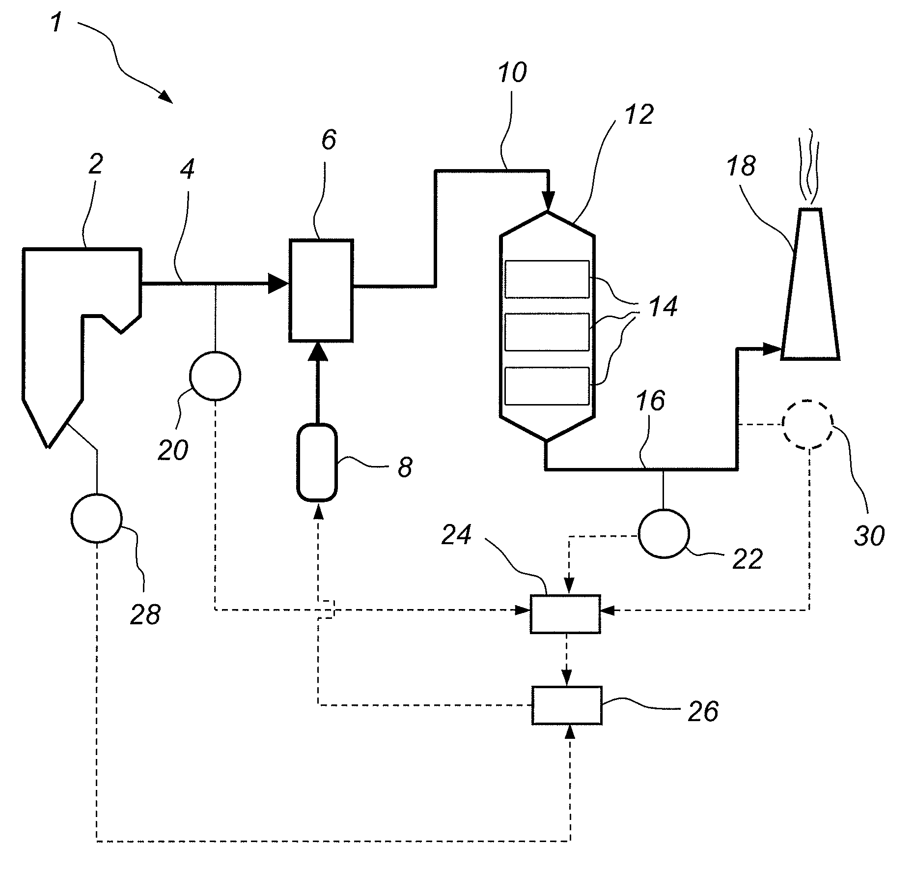
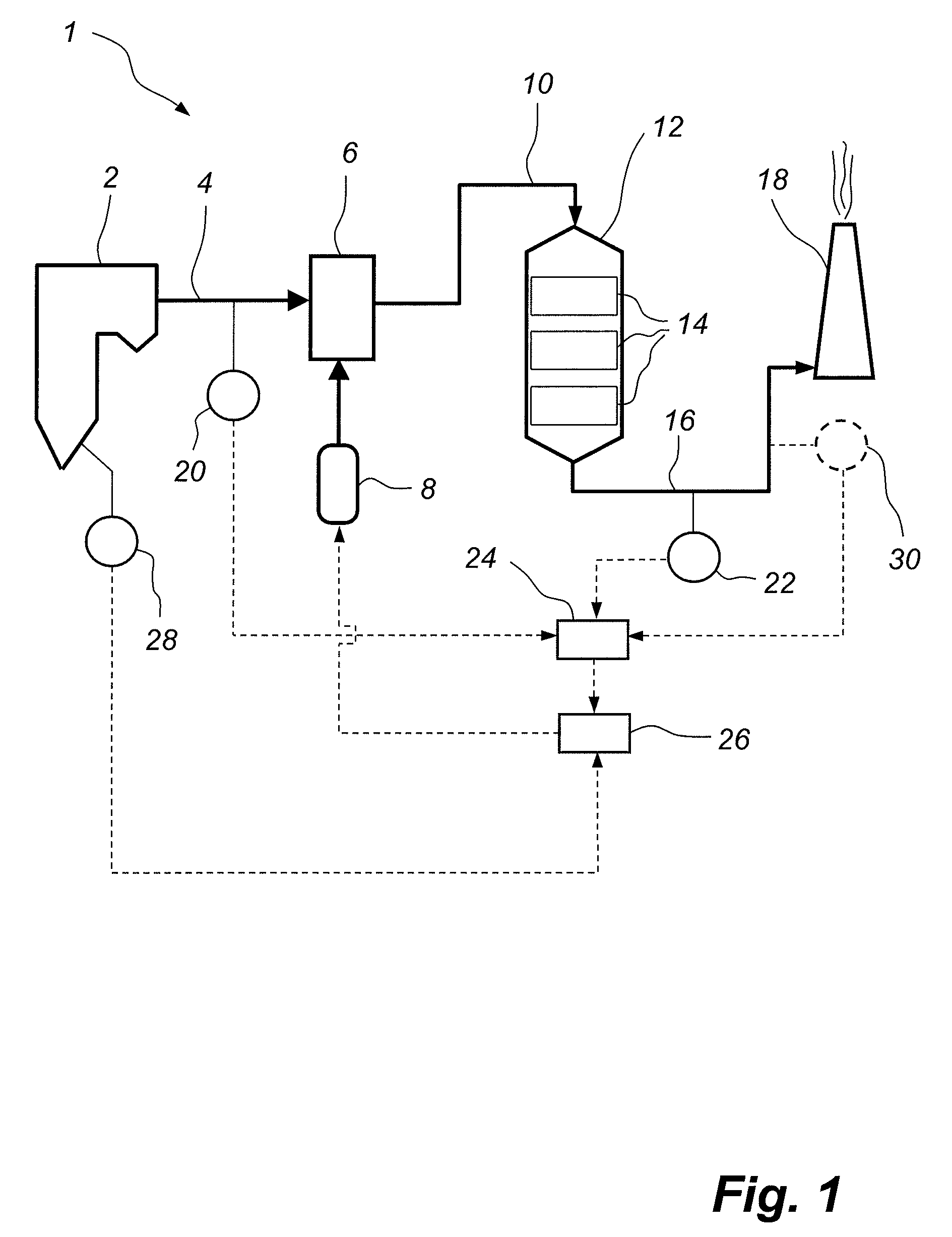
[0046]FIG. 1 is a schematic side view illustration of a power plant 1. The power plant 1 comprises a coal fired boiler 2. In the coal fired boiler 2 coal is combusted in the presence of air generating flue gases that leave the coal fired boiler 2 via a duct 4. The duct 4 forwards the flue gases to an ammonia-injection system 6. In the ammonia injection system 6 gaseous ammonia, NH3, is added to the flue gases and is thoroughly mixed with the flue gases. The gaseous ammonia is supplied to the ammonia injection system 6 from an ammonia supply system 8. The flue gases leave the ammonia injection system 6 via a duct 10 and are forwarded to a selective catalytic reduction (SCR) reactor 12. The SCR reactor 12 comprises one or more consecutive layers 14 of SCR-catalyst. This SCR catalyst comprises a catalytically active component, such as vanadium pentoxide or wolfram trioxide, applied to a ceramic carrier material so as to comprise, e.g., a honeycomb structure or a plate structure. In the...


PUM


Abstract

A method of controlling the feeding of a reducing agent, such as urea or ammonia, to a selective catalytic reduction reactor, which is operative for removing NOx from a process gas of a process plant, comprising the steps of estimating a present value of at least one predetermined parameter which is indicative of the amount of NOx that needs to be removed from said process gas in the selective catalytic reduction reactor. The rate of increase of said at least one predetermined parameter is then estimated. When said estimated rate of increase pf said at least one predetermined parameter is found to be positive, the amount of said reducing agent being supplied is increased to a higher value than would be the case if said at least one predetermined parameter were to be kept constant at the estimated present value thereof.

Description

FIELD OF THE INVENTION [0001]The present invention relates to a method of controlling the feeding of a reducing agent, such as urea or ammonia, to a selective catalytic reduction reactor which is operative for removing NOx from a process gas of a process plant, such as a combustion plant or an incineration plant, said controlling the feeding of the reducing agent comprising estimating a present value of at least one predetermined parameter which is indicative of the amount of NOx that needs to be removed from said process gas in the selective catalytic reduction reactor.[0002]The present invention further relates to a device for controlling the feeding of a reducing agent, such as urea or ammonia, to a selective catalytic reduction reactor which is operative for removing NOx from a process gas of a process plant.BACKGROUND OF THE INVENTION [0003]In the combustion of a fuel, such as coal, oil, natural gas, peat, waste, etc., in a combustion plant, such as a power plant or a waste inc...

Claims


Application Information

Patent Timeline
Patent Type & Authority Applications(United States)
IPC IPC(8): F01N9/00
CPCB01D53/8696
Inventor VANDERVEEN, DAVID P.BOYDEN, SCOTT A.
Owner GENERAL ELECTRIC TECH GMBH
Why Eureka
Try Eureka