Method and apparatus for production and maintenance of electron beam space-charge neutralization

a technology of electron beam and space charge, which is applied in the field of scanning electron beam scanners, can solve the problems of incompatible parameters, increased diameter of electron beam, and difficulty in focusing beams, so as to avoid delay

Active Publication Date: 2010-05-20
RZM TECH
View PDF2 Cites 1 Cited by
  • Summary
  • Abstract
  • Description
  • Claims
  • Application Information

AI Technical Summary

Benefits of technology

[0007]In one embodiment, an electron beam production and control assembly is provided. The electron beam production and control assembly includes a vacuum chamber having opposite rearward and forward ends, and a beam source located at the rearward end of the vacuum chamber. The beam source produces an electron beam that accumulates ions while the beam is produced. The beam source directs the beam along a path towards the forward end of the chamber. The electron beam production and control assembly also includes a target located at the forward end of the chamber. The target has an active section and an inactive section. The active section is adapted to generate x-rays that are directed through a scanner field when the beam impinges on the x-ray producing section. The electron beam production and control assembly also includes a focusing unit positioned along the chamber at a location intermediate the rearward end and the forward end. The focusing unit directs the beam towards the target in a converging manner to impinge on the target. The focusing unit sweeps the beam along a scanning path over the active section of the target. The focusing unit moves the beam to a retrace path on the inactive section of the target between sweeps of the scanning path to maintain ion accumulation in the beam between sweeps over the active section and to avoid the delay due to regeneration of the ions.

Problems solved by technology

Such parameters are mutually incompatible for an electron beam in pure vacuum where the space-charge repulsion of the beam produces much larger beam spots.
Initially, the electrons located near a center of the electron beam repel the electrons located at a radially outer edge of the electron beam causing the diameter of the electron beam to expand making focusing the beam more difficult.
However, the cryopumps and servo-valves are relatively expensive and require a sophisticated mechanical vacuum system, thus increasing the overall cost and complexity of the conventional scanning electron beam scanner.
However, when the conventional electron gun is deactivated all the positive ions accumulated in the electron beam are lost.
However, in other applications such as a cardiac scanner or a baggage handling system, the time required to re-neutralize the space charge of the electron beam may cause significant time delays that affect the overall performance of the system unless the vacuum system is operated at as high a pressure as possible.

Method used


Image

  • Method and apparatus for production and maintenance of electron beam space-charge neutralization
  • Method and apparatus for production and maintenance of electron beam space-charge neutralization
  • Method and apparatus for production and maintenance of electron beam space-charge neutralization

Examples


Embodiment Construction

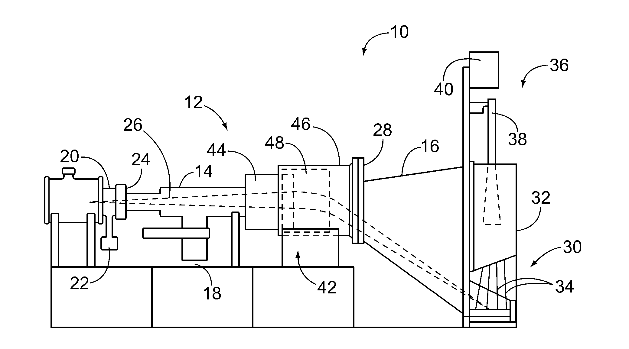
[0020]FIG. 1 is an elevation of an exemplary electron beam production and control assembly 10 in accordance with an embodiment of the present invention. The assembly 10 may be embodied as a scanning electron beam computed tomography (CT) scanner. Optionally, the assembly 10 may be embodied as a medical scanner, a baggage scanner or any other imaging device in accordance with an embodiment of the present invention. In the exemplary embodiment, the assembly 10 includes a vacuum chamber 12 that includes a first chamber section 14 and a second chamber section 16 that is disposed downstream from the first chamber section 14. As shown in FIG. 1, the assembly 10 may include a vacuum pump 18 acting on the vacuum chamber 12. In the exemplary embodiment, a beam source 20, e.g. an electron gun, which may include its own vacuum pump 22, is located at the rearward most end 24 of the vacuum chamber 12. In operation, the beam source 20 produces an electron beam 26 that is directed horizontally in ...


PUM


Abstract

An electron beam production and control assembly includes a vacuum chamber, a beam source, and a target. The target has an active section and an inactive section. The active section is adapted to generate x-rays when the beam impinges on the x-ray producing section. The electron beam production and control assembly also includes a focusing unit positioned along the chamber at a location intermediate the rearward end and the forward end. The focusing unit directs the beam towards the target in a converging manner to impinge on the target. The focusing unit sweeps the beam along a scanning path over the active section of the target. The focusing unit moves the beam to a retrace path on the inactive section of the target between sweeps of the scanning path to maintain ion accumulation in the beam between sweeps over the active section.

Description

BACKGROUND OF THE INVENTION[0001]This invention relates generally to scanning electron beam scanners and more particularly to a method and apparatus to produce and maintain electron beam space-charge neutralization.[0002]Scanning electron beam scanners, such as those used in computed tomography (CT) imaging systems, produce cross-sectional and three-dimensional (3D) images of the human body and objects such as baggage and cargo. The scanning electron beam permits fast scan speeds, e.g. 50 msec / scan, so that rapidly moving objects such as the human heart can be imaged.[0003]Conventional scanning electron beam scanners include an electron gun that produces an electron beam inside a highly evacuated chamber. The electron beam expands from its point of origin, e.g. the electron gun, because of the mutual electrostatic repulsion of the electrons in the beam. Where the beam is sufficiently large, it passes through a magnetic lens and a dipole deflecting magnet which scans the electron bea...

Claims


Application Information

Patent Timeline
Patent Type & Authority Applications(United States)
IPC IPC(8): H01J3/14
CPCH01J35/08H01J35/14H01J35/30H01J2235/20H01J37/3007H01J2235/086H01J37/026H01J35/112H01J35/153
Inventor RAND, ROY E.
Owner RZM TECH
Why Eureka
Try Eureka