Temperature sensor

a temperature sensor and sensor technology, applied in the field of temperature sensors, can solve the problems of inability to generate pulse width that is accurately dependent on temperature, deviating from its theoretical value, and low precision of temperature measurement, and achieve the effect of precise temperature measuremen

Active Publication Date: 2010-05-20
ABLIC INC
View PDF4 Cites 20 Cited by
  • Summary
  • Abstract
  • Description
  • Claims
  • Application Information

AI Technical Summary

Benefits of technology

[0023]According to the present invention, even when the manufacturing fluctuations are present, by switching the connections between the MOS transistors included in a current source circuit and the bipolar transistors, variations in current values containing offsets between the above-mentioned MOS transistors due to the manufacturing fluctuations are ave

Problems solved by technology

However, due to manufacturing fluctuations in capacitor C1, the temperature is measured with low precision.
However, due to manufacturing fluctuations in bipolar transistors and MOS transistors, a value of the current IIPTAT deviates from its theoretical value.
As a result, the charge to the capacitor C1 varies, and hence a pulse width that is accurately dependent on temperature cannot be generated.
Thus, measurement precision cannot be improved by merely using a ratio between the current IIPTAT and the current Iref.
Therefore, in a circuit for generatin

Method used


Image

  • Temperature sensor
  • Temperature sensor
  • Temperature sensor

Examples


first embodiment

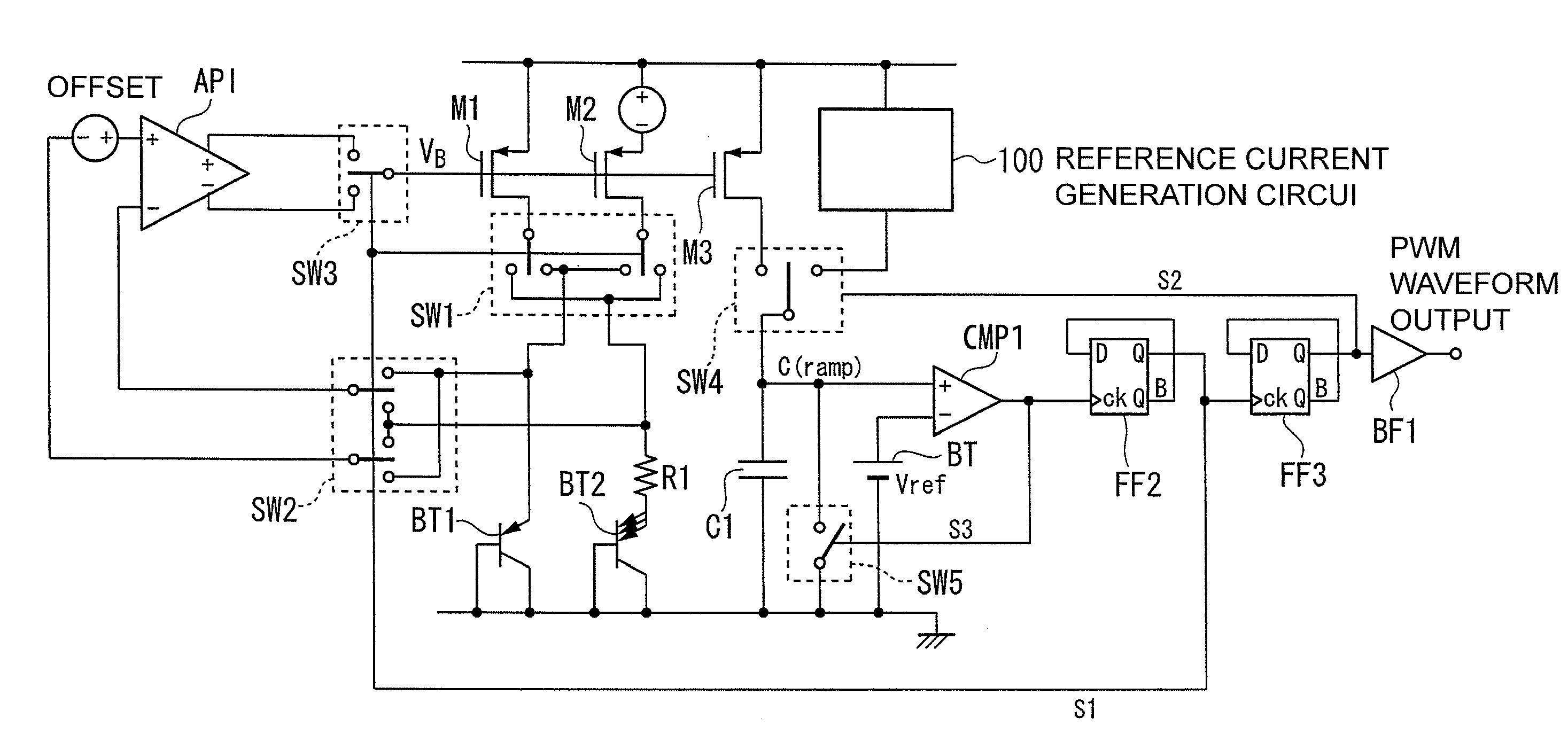
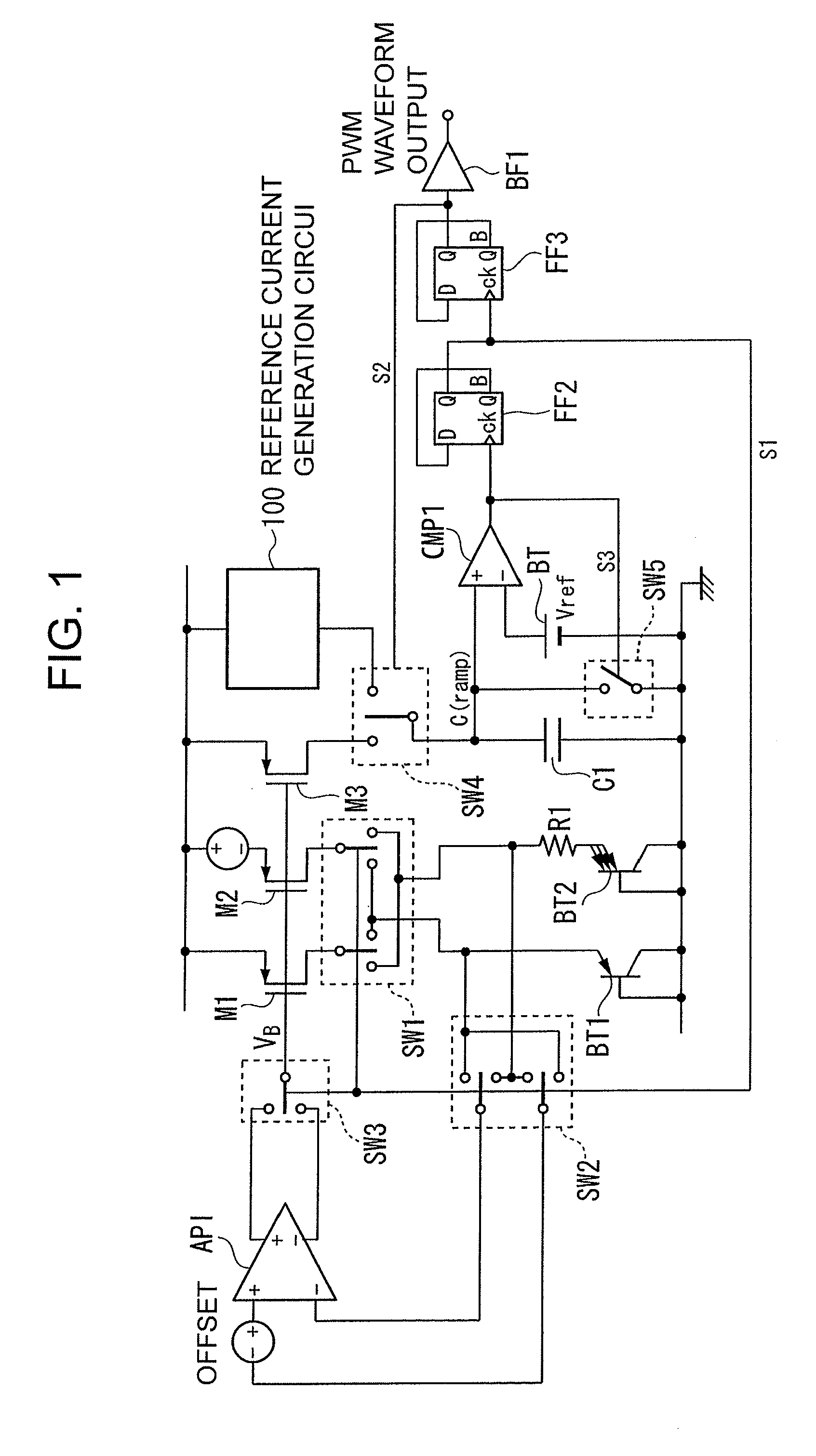
[0037]Hereinafter, referring to the accompanying drawings, a temperature sensor according to a first embodiment of the present invention is described. FIG. 1 is a block diagram illustrating a configuration example of the temperature sensor according to the first embodiment of the present invention.

[0038]In FIG. 1, P-channel MOS transistors M1 and M2 form a current source circuit. Each of the MOS transistors M1 and M2 has a source applied with a power supply voltage. Further, a P-channel MOS transistor M3, which is described later, has a gate applied with the same bias voltage as that applied to gates of the MOS transistors M1 and M2 forming the current source circuit described above, to thereby establish a current source connection.

[0039]A bipolar transistor BT1 is a PNP bipolar transistor connected as a load of one of the above-mentioned MOS transistors M1 and M2.

[0040]A bipolar transistor BT2 is a PNP bipolar transistor connected as a load of another one of the MOS transistors M1 ...

second embodiment

[0132]Next, referring to the accompanying drawings, a temperature sensor according to a second embodiment of the present invention is described. FIG. 6 is a block diagram illustrating a configuration example of the temperature sensor according to the second embodiment of the present invention.

[0133]The same component as that of FIG. 1 illustrating the first embodiment is denoted by the same reference symbol, and description thereof is omitted. Hereinafter, only a configuration and an operation according to the second embodiment different from those of the first embodiment are described.

[0134]A newly-added component is a flip-flop FF5.

[0135]The flip-flop FF5 is provided at a subsequent stage of the flip-flop FF3. A data terminal D and an output terminal QB of the flip-flop FF5 are connected with each other so that the flip-flop FF5 may function as a toggle flip-flop. The flip-flop FF5 has a clock terminal CK that is connected to the output terminal Q of the flip-flop FF3 and receives...

third embodiment

[0153]Next, referring to the accompanying drawings, a temperature sensor according to a third embodiment of the present invention is described. FIG. 8 is a block diagram illustrating a configuration example of the temperature sensor according to the third embodiment of the present invention.

[0154]The same component as that of FIG. 6 illustrating the second embodiment is denoted by the same reference symbol, and description thereof is omitted. Hereinafter, only a configuration and an operation according to the third embodiment different from those of the second embodiment are described.

[0155]In the third embodiment of the present invention, a newly-added component is a selection switch SW6.

[0156]Further, in the third embodiment, a capacitor C1A and a capacitor C1B are provided instead of the capacitor C1 according to the second embodiment. Similarly, a selection switch SW4A and a selection switch SW4B are provided instead of the selection switch SW4 according to the second embodiment...


PUM


Abstract

Provided is a temperature sensor capable of performing more precise temperature measurement compared to conventional ones, even when manufacturing fluctuations are present in semiconductor elements forming a circuit for generating a temperature-dependent current. The temperature sensor includes: a temperature-dependent voltage generation circuit for generating a temperature-dependent potential that is dependent on temperature; a current generation circuit for allowing a temperature-dependent current to flow based on the temperature-dependent potential; a reference current generation circuit for generating a reference current that is independent of temperature; a capacitor that is charged alternately with the temperature-dependent current during a first charge period and the reference current during a second charge period; a pulse generation circuit for comparing a charged voltage of the capacitor with a reference voltage to generate a pulse; and a control circuit for alternately supplying the temperature-dependent current and the reference current to the capacitor. The temperature-dependent voltage generation circuit includes switches for switching connection relations between MOS transistors forming a current source circuit included in the temperature-dependent voltage generation circuit and bipolar transistors each serving as a load of the current source circuit.

Description

RELATED APPLICATIONS[0001]This application claims priority under 35 U.S.C. §119 to Japanese Patent Application No. 2008-292512 filed on Nov. 14, 2008, the entire content of which is hereby incorporated by reference.BACKGROUND OF THE INVENTION[0002]1. Field of the Invention[0003]The present invention relates to a temperature sensor formed on a semiconductor device, and more particularly, to a temperature sensor for measuring ambient temperature of a semiconductor device.[0004]2. Description of the Related Art[0005]Conventionally, a thermometer utilizing a semiconductor device has been used for measuring an ambient temperature change or body temperature.[0006]For example, there is known a technology of adjusting a circuit operation by controlling an oscillation frequency in accordance with temperature changes (see, for example, JP 2006-101489 A), and there is also known a temperature sensor that is capable of indicating temperature using the controlled oscillation frequency itself (ht...

Claims


Application Information

Patent Timeline
IPC IPC(8): G01K7/00
CPCG01K7/01H02M3/00H03K3/282H03K17/14
Inventor YOSHIKAWA, KIYOSHI
Owner ABLIC INC
Why Eureka
Try Eureka