Transmission device with a hydraulic system comprising a transmission main pump apparatus

a transmission device and hydraulic system technology, applied in the direction of pump control, gearing control, gearing elements, etc., can solve the problems of insufficient loading of transmission components, limited towing ability, and limited towing speed and towing distance, so as to achieve a small structural space occupation

Active Publication Date: 2010-05-20
ZF FRIEDRICHSHAFEN AG
View PDF8 Cites 11 Cited by
  • Summary
  • Abstract
  • Description
  • Claims
  • Application Information

AI Technical Summary

Benefits of technology

[0011]Accordingly, the purpose of the present invention is to provide a transmission device in which, to avoid operating situations that have an adverse effect on the friction of the transmission, transmission components can be supplied to the desired extent with hydraulic fluid even during towing processes or during operating condition variations comparable thereto, inexpensively and with little structural space occupation.

Problems solved by technology

Without special measures both the towing speeds and the towing distances are usually very limited, but this is undesirable.
The limited towing ability is the result of insufficient supply of the transmission components with hydraulic fluid by the main transmission pump when the drive machine is switched off, since during a towing process, while the drive wheels are in contact with the ground, a torque is transferred into the transmission device via a transmission output shaft and transmission components actively connected to the transmission output shaft are driven in rotation.
Owing to the deficient lubrication and cooling of these driven transmission components, the frictional heat generated in the area of the transmission components during a towing process can only be dissipated to a limited extent, so that the thermal loading of the transmission components becomes undesirably high and sometimes seizing that permanently compromises the operation of the transmission device can take place.
The problems that result from inadequate supply of hydraulic fluid to a transmission device can sometimes also occur during other operating condition variations of a vehicle, depending on the design of the vehicle's drivetrain.
For example, a transmission device as described earlier in a hybrid all-wheel-drive vehicle may likewise not be supplied to the desired extent with hydraulic fluid from a main transmission pump device arranged on the transmission input side, during purely electric driving operation by an electric machine which is directly associated with a vehicle axle without having to pass the drive torque of the electric machine via the transmission device.
Disadvantageously, compared with transmission devices made without an auxiliary pump device, the last-mentioned design of transmission devices with a respective main transmission pump that can be driven by a drive engine and an auxiliary pump preferably driven by an electric motor increases the production costs of a transmission device.
Furthermore, in unfavorable operating situations the current uptake of an active auxiliary pump device places an undesirably high load on the vehicle's electric system.
In addition, the arrangement of the auxiliary pump preferably on the outside of the housing of the transmission device takes up structural space in the vehicle and entails construction costs and effort for the hydraulic connection of the auxiliary pump to a hydraulic system of the transmission device and for the electrical connection of the auxiliary pump to the electric control and regulating system of a drivetrain of a vehicle, to an undesired extent.
The active connection between the transmission and the drive output can be broken for example by disconnecting the cardan shaft or by some other suitable measure, but vehicle drivetrains made in this way are again characterized by high production costs and are of complex design.

Method used


Image

  • Transmission device with a hydraulic system comprising a transmission main pump apparatus
  • Transmission device with a hydraulic system comprising a transmission main pump apparatus

Examples


Embodiment Construction

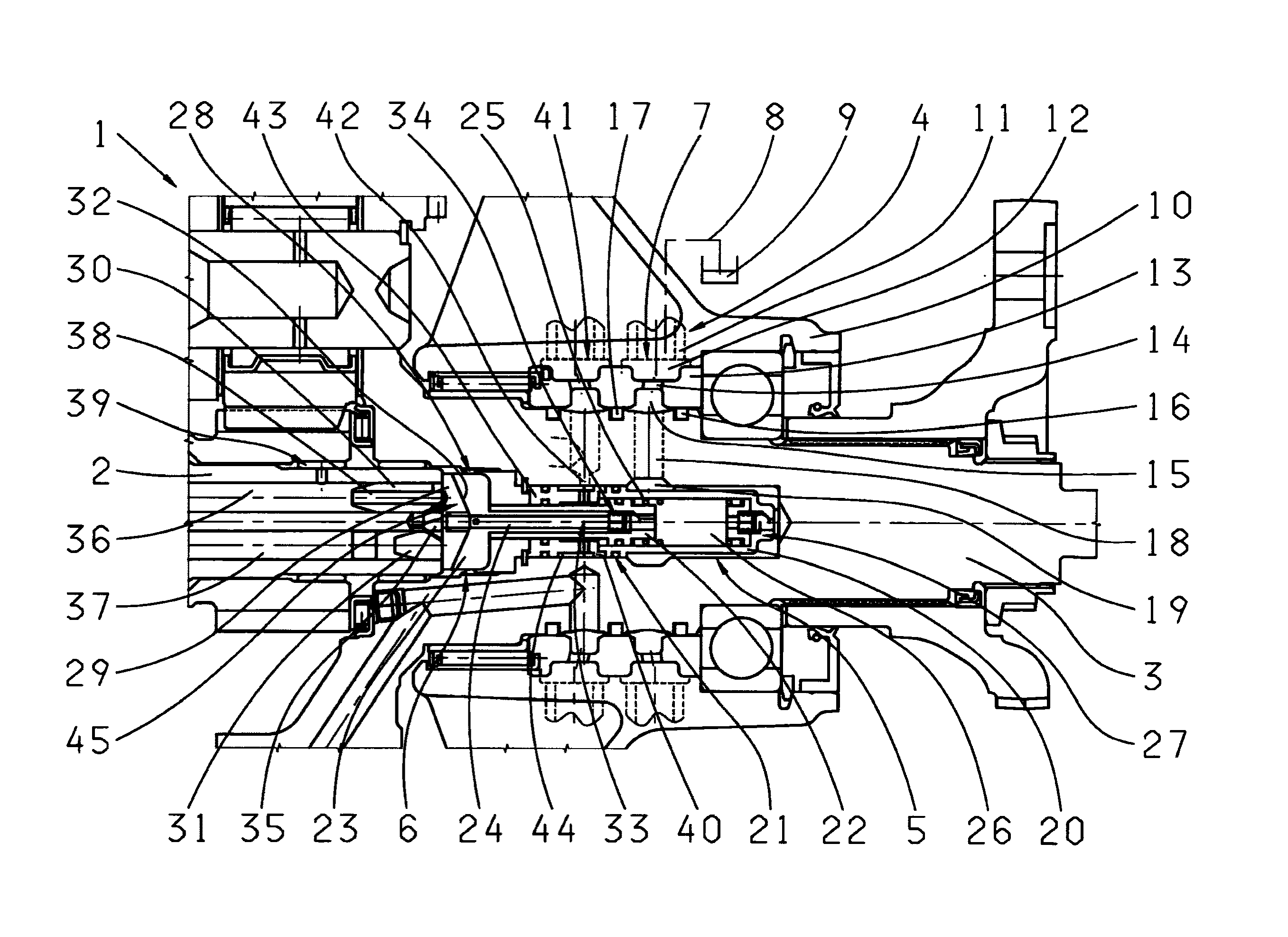
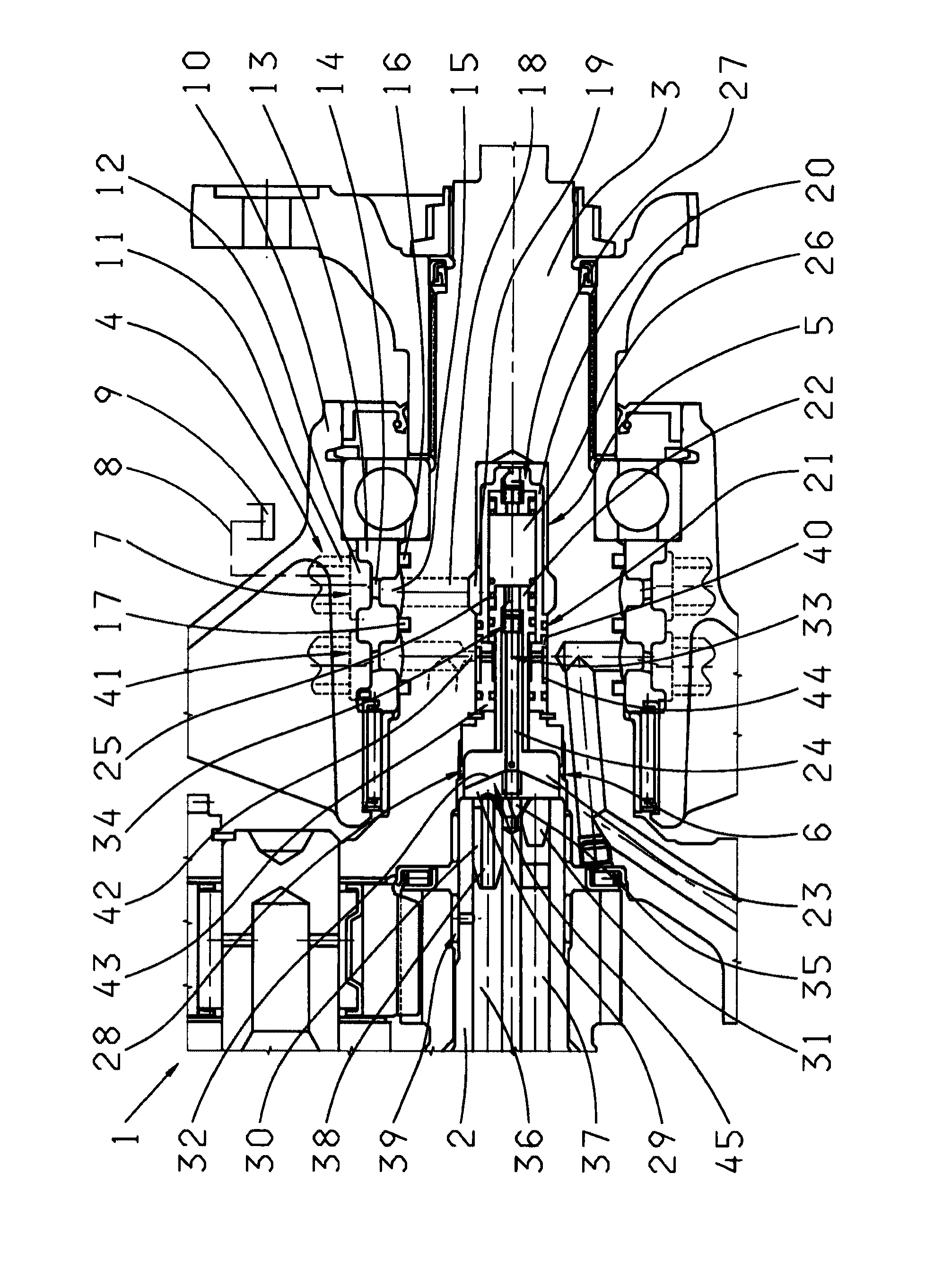
[0029]The FIGURE represents a greatly simplified, partial longitudinally sectioned view of a transmission device 1 with a transmission input shaft 2, a main transmission shaft and a transmission output shaft 3. The transmission device 1 is made with a hydraulic system 4 by which various transmission components can be supplied with hydraulic fluid. The hydraulic system 4 is made with a main transmission pump device arranged on the transmission input side and not shown in the FIGURE, which can be driven by a torque applied to the transmission input shaft 2 in a manner known per se.

[0030]A force flow between the transmission input shaft 2 and the transmission output shaft 3 can be produced by means of various hydraulically actuated transmission components, i.e. in the present case by frictional shift elements such as disk clutches and disk brakes. In the transmission device 1 the force flow is interrupted when the hydraulic system 4 is not supplied by the main transmission device, this...


PUM


Abstract

A transmission device (1) with a hydraulic system (4) comprising a main transmission pump device for supplying various transmission components with hydraulic fluid. The main transmission pump device is driven by torque applied to the transmission input shaft (2). A force flow between the transmission input shaft (2) and transmission output shaft (3) is produced by various hydraulically actuated transmission components. When the hydraulic system (4) is not supplied by the main transmission pump, the force flow is interrupted. The hydraulic system (4) has an auxiliary pump device (5) by virtue of which the hydraulic system (4) too can be supplied with hydraulic fluid. The auxiliary pump device (5) is driven by torque applied to the transmission output shaft (3) at least when the force flow is interrupted.

Description

[0001]This application claims priority from German patent application serial no. 10 2008 043 734.4 filed Nov. 14, 2008.FIELD OF THE INVENTION[0002]The invention concerns a transmission device with a hydraulic system comprising a main transmission pump device.BACKGROUND OF THE INVENTION[0003]Transmission devices known from practice, in particular automatic transmissions, are made with a hydraulic system comprising a main transmission pump for the supply of hydraulic fluid to various transmission components. Such main transmission pumps are often arranged on the transmission input side and can be driven by a torque applied to a transmission input shaft, for example by torque from a drive machine of a vehicle drivetrain. A force flow can be produced between the transmission input shaft and a transmission output shaft by various respective hydraulically actuated transmission components, this force flow being interrupted when the hydraulic system is not supplied by the main transmission ...

Claims


Application Information

Patent Timeline
Patent Type & Authority Applications(United States)
IPC IPC(8): B60W10/10F04B49/20
CPCY10T477/688F16H61/0031
Inventor LIST, MATTHIASSCHMIDT, THILOLINDNER, THOMASTIESLER, PETER
Owner ZF FRIEDRICHSHAFEN AG
Why Eureka
Try Eureka