Method and apparatus for generating electricity

a technology of electricity generation and apparatus, applied in the direction of electric apparatus, climate sustainability, efficient propulsion technologies, etc., can solve the problems of limiting the usefulness of a microturbine for applications, reducing efficiency rapidly, and difficult to design and maintain the maximum energy input through a solar collector. achieve the effect of increasing the mass of high-pressure working fluid, increasing the temperature and enthalpy of working fluid, and lowering the temperatur

Inactive Publication Date: 2010-05-27
SMITH DOUGLAS W P
View PDF14 Cites 19 Cited by
  • Summary
  • Abstract
  • Description
  • Claims
  • Application Information

AI Technical Summary

Benefits of technology

[0018]According to the present invention there is provided a method of converting energy into electricity using a gaseous working fluid and an evaporative fluid, comprising steps of: pressuring the gaseous working fluid in a compressor; heating the high-pressure working fluid in a recuperator by heat exchange with low-pressure working fluid emerging from a turbine; adding energy to the high-pressure working fluid to increase the temperature and enthalpy of the working fluid; expanding the working fluid through the turbine, using the turbine to generate electricity; and cooling the low-pressure working fluid emerging from the turbine in the recuperator, the method further comprising lowering the temperature and increasing the mass of the high-pressure working fluid after leaving the compressor, and/or after leaving the recuperator, by introducing the evaporative fluid to produce evaporative cooling.
[0019]The invention also provides an apparatus for converting energy into electricity using a gaseous working fluid and an evaporative fluid, comprising: a compressor for pressurizing the working fluid; a recuperator to heat the pressurized working fluid by heat exchange with low-pressure working fluid leaving a turbine; an energy source for increasing the temperature and enthalpy of the pressurized recuperated working fluid; a turbine for expanding the pressurized recuperated working fluid from the energy source to a low-pressure working fluid; an electrical generator coupled to the turbine; and means for conveying the low-pressure working fluid emerging from the turbine to the recuperator; the apparatus further comprising means for lowering the temperature and increasing the mass of the high-pressure working fluid after leaving the compressor, and/or after leaving the recuperator, by introducing the evaporative fluid to produce evaporative cooling.
[0020]The invention also provides a method for converting energy into electricity using a gas as working fluid and an evaporative fluid, wherein the working fluid and the evaporative fluid are captured in a closed cycle, the method comprising steps of: pressuring the gaseous working fluid mixture which is saturated with evaporative fluid vapour in a compressor which causes an increase in pressure and temperature of the working fluid; adding a portion of the evaporative fluid liquid from a preheater to cause evaporative cooling and mass increase of the working fluid vapor; heating the high-pressure working fluid mixture in a recuperator; adding the balance of the evaporative fluid liquid from the preheater to cause cooling and further mass increase of the working fluid vapor; conveying the h...

Problems solved by technology

This is strictly due to the high percentage of energy used to operate the compressor at full power and operating at constant speed which requires a constant parasitic energy requirement.
This limits the usefulness of a microturbine for applications in which full power is not always needed or can be tolerated.
The efficiency reduces rapidly since the parasitic compressor load represents an increasing portion of the total turbine power.
The turndown issue for the solar microturbine shown in FIG. 2 is more influential than for the microturbine shown in FIG. 1 since, in practice, it is diffi...

Method used


Image

  • Method and apparatus for generating electricity
  • Method and apparatus for generating electricity
  • Method and apparatus for generating electricity

Examples


Embodiment Construction

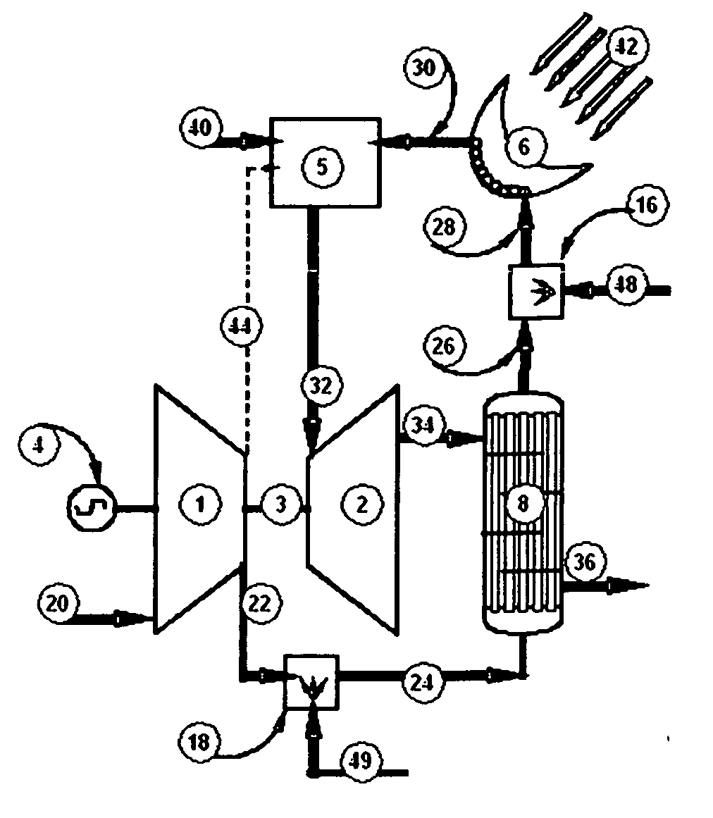
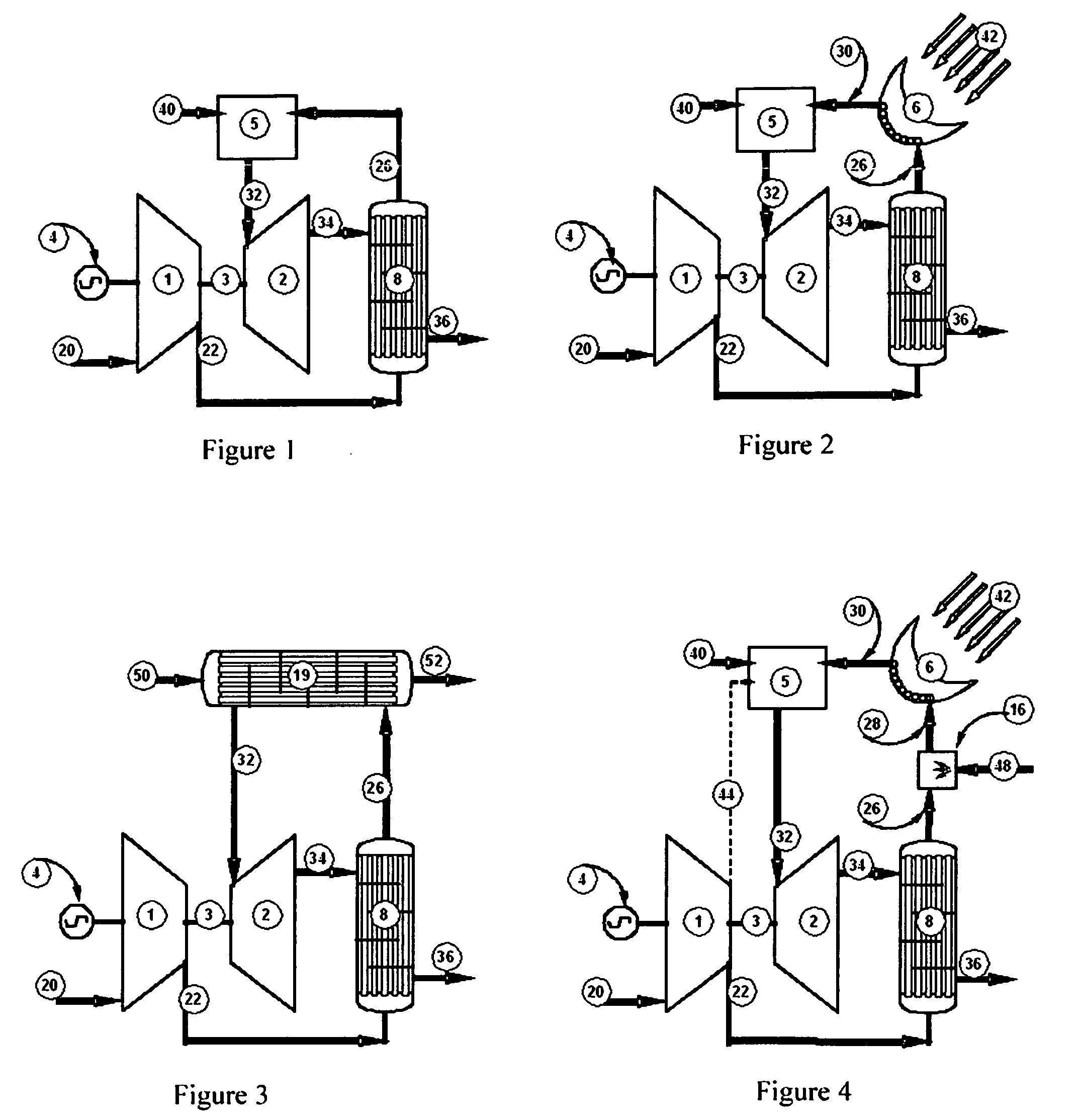
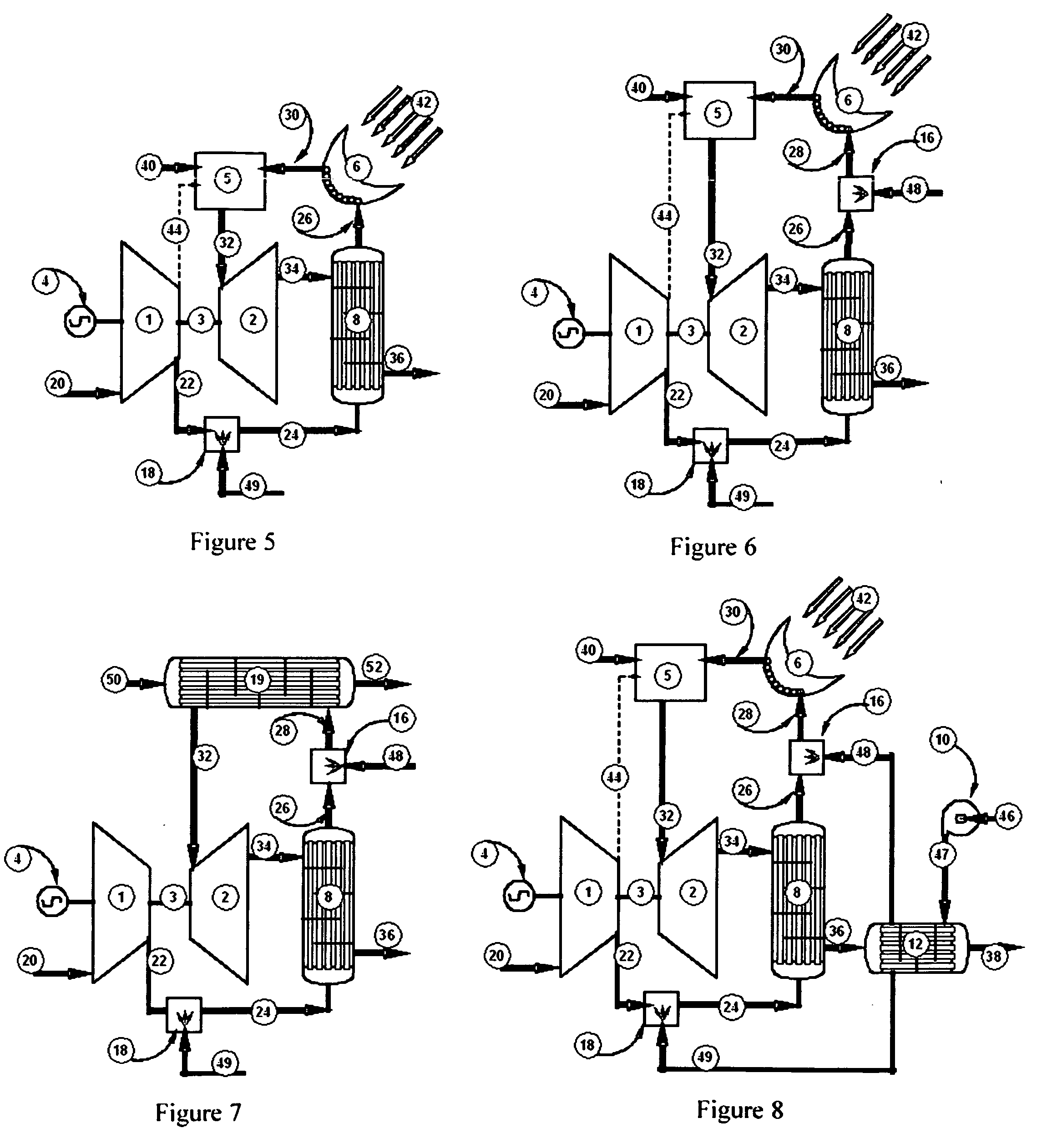
[0040]Thermodynamic analysis of the microturbine shown in FIG. 1 is substantially equal to the thermodynamic analysis of the solar microturbine shown in FIG. 2 which reveals a maximum overall efficiency of 26% and a turndown characteristic shown in FIG. 11. Extension of this graph indicates that a 35% reduction of input energy would reduce the output power to zero. Characteristics of the solar microturbine shown in FIG. 2 will serve as the baseline of comparison for hybrid Brayton modifications taught by this patent disclosure. The following discussions made in comparison to the solar microturbine shown in FIG. 2 will apply equally to effects on the microturbine shown in FIG. 1. Discussions of effects of the hybrid Brayton modifications on the externally heated microturbine shown in FIG. 3 will highlight the implication of the temperature dependent nature of heat transfer in the external heater.

[0041]The hybrid Brayton modification shown in FIG. 4 includes adding water (48) into cha...


PUM


Abstract

A method of converting energy into electricity using a gaseous working fluid and an evaporative fluid comprises pressuring the working fluid (20) in a compressor (1), heating the high-pressure working fluid (22) in a recuperator (8) using thermal energy in low-pressure working fluid (34) emerging from a turbine (2), adding energy from an energy source (5, 6) to increase the temperature and enthalpy of the working fluid (32), expanding the working fluid (32) through the turbine (2), using the turbine to generate electricity, and cooling the low-pressure working fluid (34) emerging from the turbine in the recuperator. The method further comprises lowering the temperature and increasing the mass of the high-pressure working fluid (22) after leaving the compressor (1), and/or after leaving the recuperator (8), by introducing the evaporative fluid (48, 49) to produce evaporative cooling.

Description

PRIORITY CLAIM & CITATION[0001]This application claims priority from U.S. patent application Ser. No. 12 / 284,226 filed Sep. 18, 2008.TECHNICAL FIELD OF THE INVENTION[0002]This invention relates to the field of electricity generation using a modified form of the thermodynamic power cycle known as the Brayton cycle, conventionally used in gas turbines and jet engines.BACKGROUND OF THE INVENTION[0003]Gas turbines used for power generation are designed over a wide range of power outputs and with a variety of configurations and operating conditions. They operate using the Brayton cycle which is a single-phase vapor power cycle. Typical systems are open-loop using atmospheric air as the working fluid. In the Brayton cycle air is compressed then fuel is added and combusted then the combined air and combustion gases are expanded through a turbine. A portion of the work produced by the turbine is used for compression of the incoming air with the balance of the turbine work being made availab...

Claims


Application Information

Patent Timeline
IPC IPC(8): F03G6/00G21D5/00F01K23/06F01D15/10
CPCF01K7/16F01K21/04F02C1/05F02C6/18Y02T50/675Y02E10/46Y02E20/14Y02T50/671F02C7/141Y02T50/60
Inventor SMITH, DOUGLAS W. P.
Owner SMITH DOUGLAS W P
Why Eureka
Try Eureka