
Integrated hybrid heat exchanger with multi-sectional structure

a heat exchanger and hybrid technology, applied in indirect heat exchangers, machines/engines, light and heating apparatus, etc., can solve the problems of thermal shock, deterioration of electrical components efficiency, and reduced output power during electrical components operation, so as to improve overall cooling efficiency and durability, reduce thermal shock

Active Publication Date: 2010-05-27
HANON SYST +1
View PDF20 Cites 17 Cited by
  • Summary
  • Abstract
  • Description
  • Claims
  • Application Information

AI Technical Summary

Benefits of technology

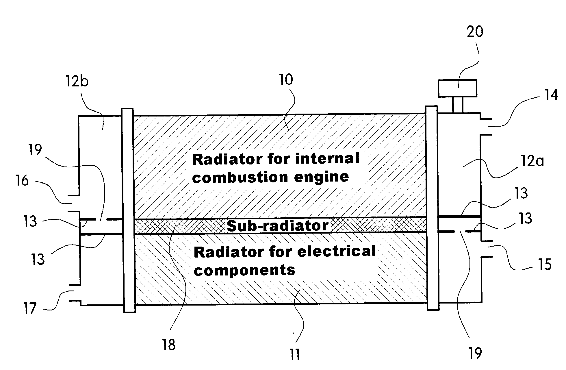
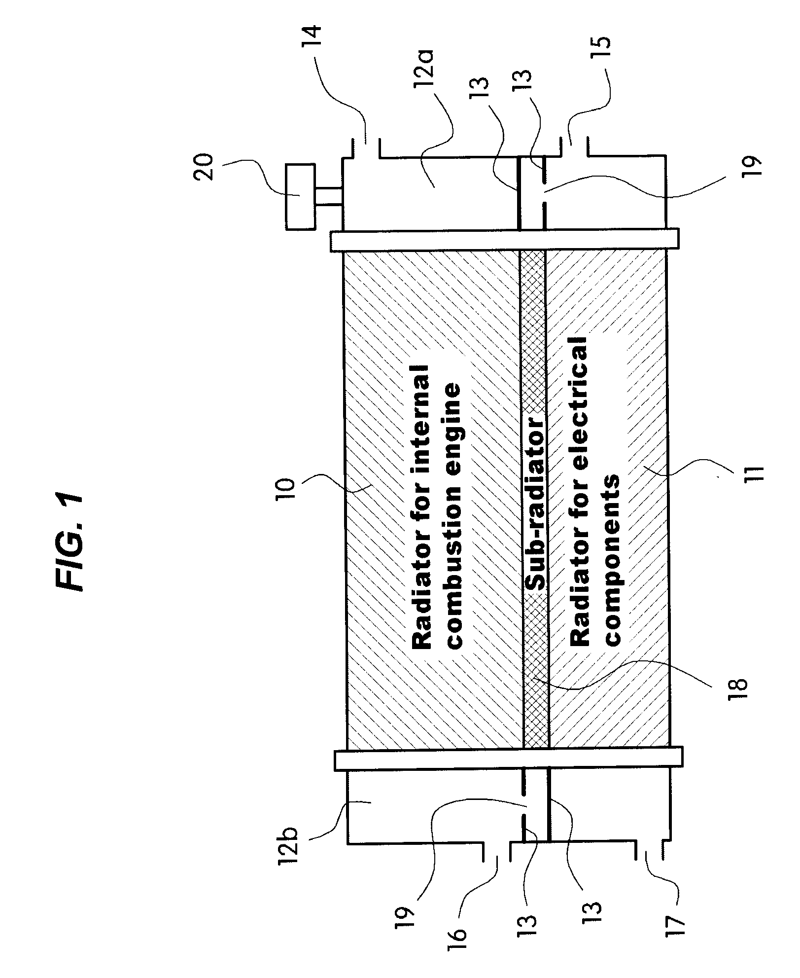
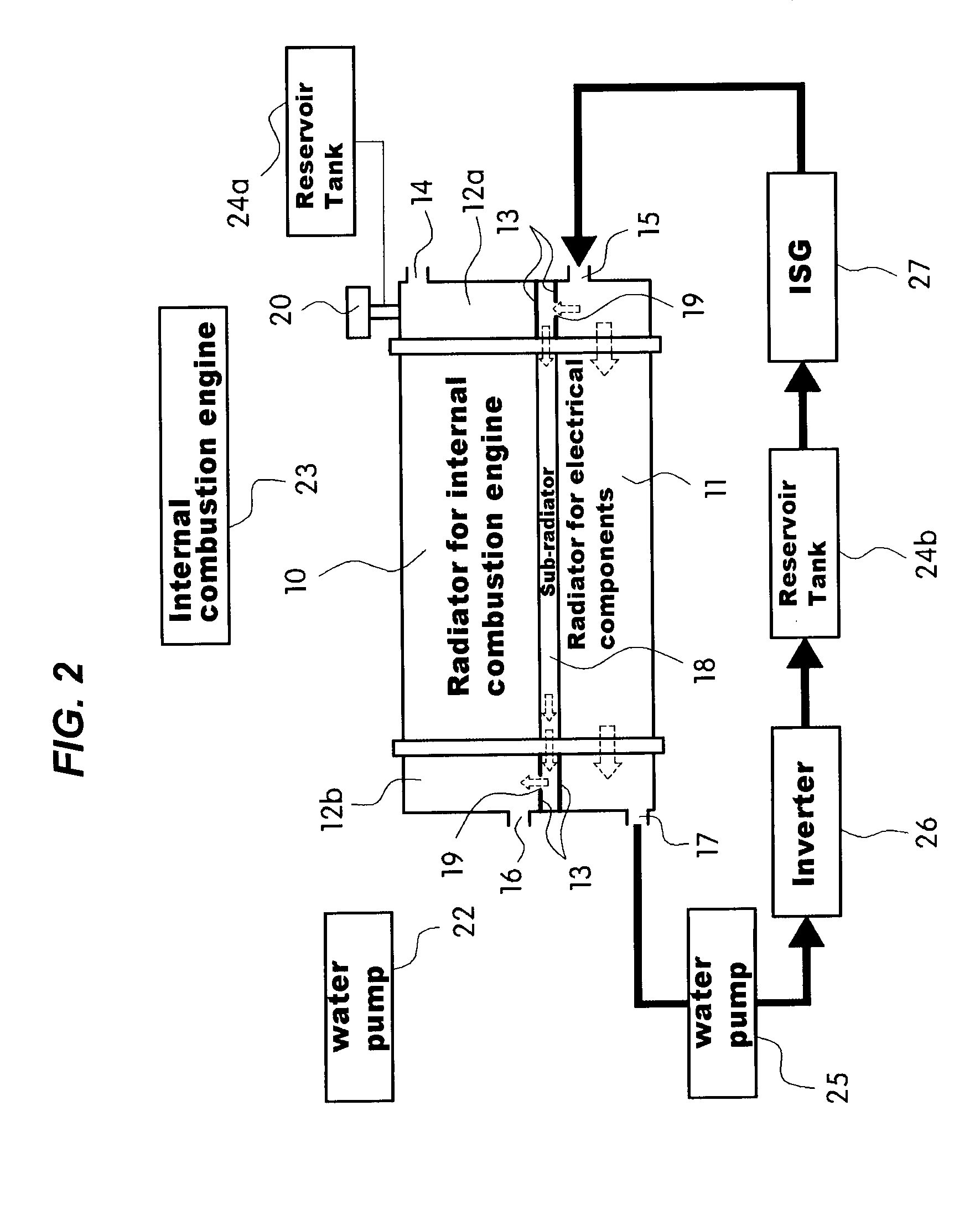
[0019]Various aspects of the present invention are directed to provide an integrated hybrid heat exchanger with a multi-sectional structure, in which a radiator for electrical components and a radiator for an internal combustion engine are integrated into a single structure, in which each of the two radiators has an independent coolant flow structure in which the flow of liquid fluid is reduced by a pressure difference between the two radiators such that coolant in the radiator for the internal combustion engine and coolant in the radiator for the electrical components are not mixed with each other, and a sub-radiator having a connection structure that serves as a buffer between the radiator for the electrical components and the radiator for the internal combustion engine is provided to prevent thermal shock and provide thermal resistance. Therefore, it is possible to effectively reduce the thermal shock and improve the thermal resistance to thermal conduction, thus improving the overall cooling efficiency and durability.

Problems solved by technology

As a result, the temperature of the radiator for the electrical components is increased, which deteriorates the efficiency of electrical components reduces the output power during operation of the electrical components.
), heated by the operation of the electrical components is suddenly supplied to the radiator for the electrical components, the contractile force at the lower temperature side and the expansive force at the higher temperature side are simultaneously generated at the diaphragm portion, the core portion, and a bonding portion between the core and header, thus causing thermal shock.
If such a situation continues for a long time, it may cause leakage due to fatigue at the direct contact portions.

Method used


Image

  • Integrated hybrid heat exchanger with multi-sectional structure
  • Integrated hybrid heat exchanger with multi-sectional structure
  • Integrated hybrid heat exchanger with multi-sectional structure

Examples


Embodiment Construction

[0037]Reference will now be made in detail to various embodiments of the present invention(s), examples of which are illustrated in the accompanying drawings and described below. While the invention(s) will be described in conjunction with exemplary embodiments, it will be understood that present description is not intended to limit the invention(s) to those exemplary embodiments. On the contrary, the invention(s) is / are intended to cover not only the exemplary embodiments, but also various alternatives, modifications, equivalents and other embodiments, which may be included within the spirit and scope of the invention as defined by the appended claims.

[0038]FIG. 1 is a schematic diagram showing an integrated hybrid heat exchanger with a multi-sectional structure in accordance with various embodiments of the present invention.

[0039]As shown in FIG. 1, in a hybrid cooling system including two cooling systems such as an electrical component cooling system and an internal combustion en...


PUM


Abstract

An integrated hybrid heat exchanger with a multi-sectional structure, may include a first radiator and a second radiator, and / or at least a coolant bypass member disposed between the first and second radiators, the coolant bypass member connecting one end portion of the first radiator and the other end portion of the second radiator so as to fluid-communicate between the first radiator and the second radiator.

Description

CROSS-REFERENCE TO RELATED APPLICATION[0001]The present application claims priority to Korean Patent Application No. 10-2008-0115983 filed Nov. 21, 2008, the entire contents of which application is incorporated herein for all purposes by this reference.BACKGROUND OF THE INVENTION[0002]1. Field of the Invention[0003]The present disclosure relates to an integrated hybrid heat exchanger for a hybrid vehicle. More particularly, it relates to an integrated hybrid heat exchanger with a multi-sectional structure, in which an electrical component cooling system and an internal combustion engine cooling system are integrated into a single cooling system and a radiator for preventing thermal shock and providing thermal resistance is provided to improve cooling efficiency and durability.[0004]2. Description of Related Art[0005]In general, a hybrid vehicle is a vehicle that is equipped with an internal combustion engine and a motor such that the vehicle is driven by one or both of the engine an...

Claims


Application Information

Patent Timeline
IPC IPC(8): B60H1/32F28D21/00F01P9/00B60L50/16
CPCB60H1/00328B60H1/00385F01P3/18F28D2021/0094F28D1/0417F28D1/0443F01P2050/24F01P3/12F01P3/20F01P11/18B60L50/16
Inventor MIN, EUN KICHO, BYOUNG SUNCHA, YONG WOONGKIM, JAE YEON
Owner HANON SYST
Learn More