Method of removing coating resin layer of resin-coated metal tube

a metal tube and coating resin technology, applied in the direction of machines/engines, mechanical equipment, manufacturing tools, etc., can solve the problems of large and the surface roughness of the resin layer after stripping becomes large, so as to achieve the effect of high metal reflectivity, and little effect on the plating layer

a metal tube and coating resin technology, applied in the direction of machines/engines, mechanical equipment, manufacturing tools, etc., can solve the problems of large and the surface roughness of the resin layer after stripping becomes large, so as to achieve the effect of high metal reflectivity, and little effect on the plating layer

US20100126972A1Active Publication Date: 2010-05-27SANOH IND CO LTD

Image

  • Method of removing coating resin layer of resin-coated metal tube
  • Method of removing coating resin layer of resin-coated metal tube
  • Method of removing coating resin layer of resin-coated metal tube

Examples


Embodiment Construction

[0017]Below, an embodiment of the method of removing a coating resin layer of a resin-coated metal tube relating to the present invention described above is explained in detail with reference to drawings.

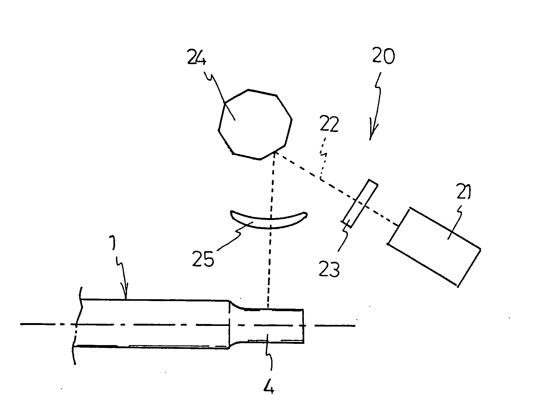
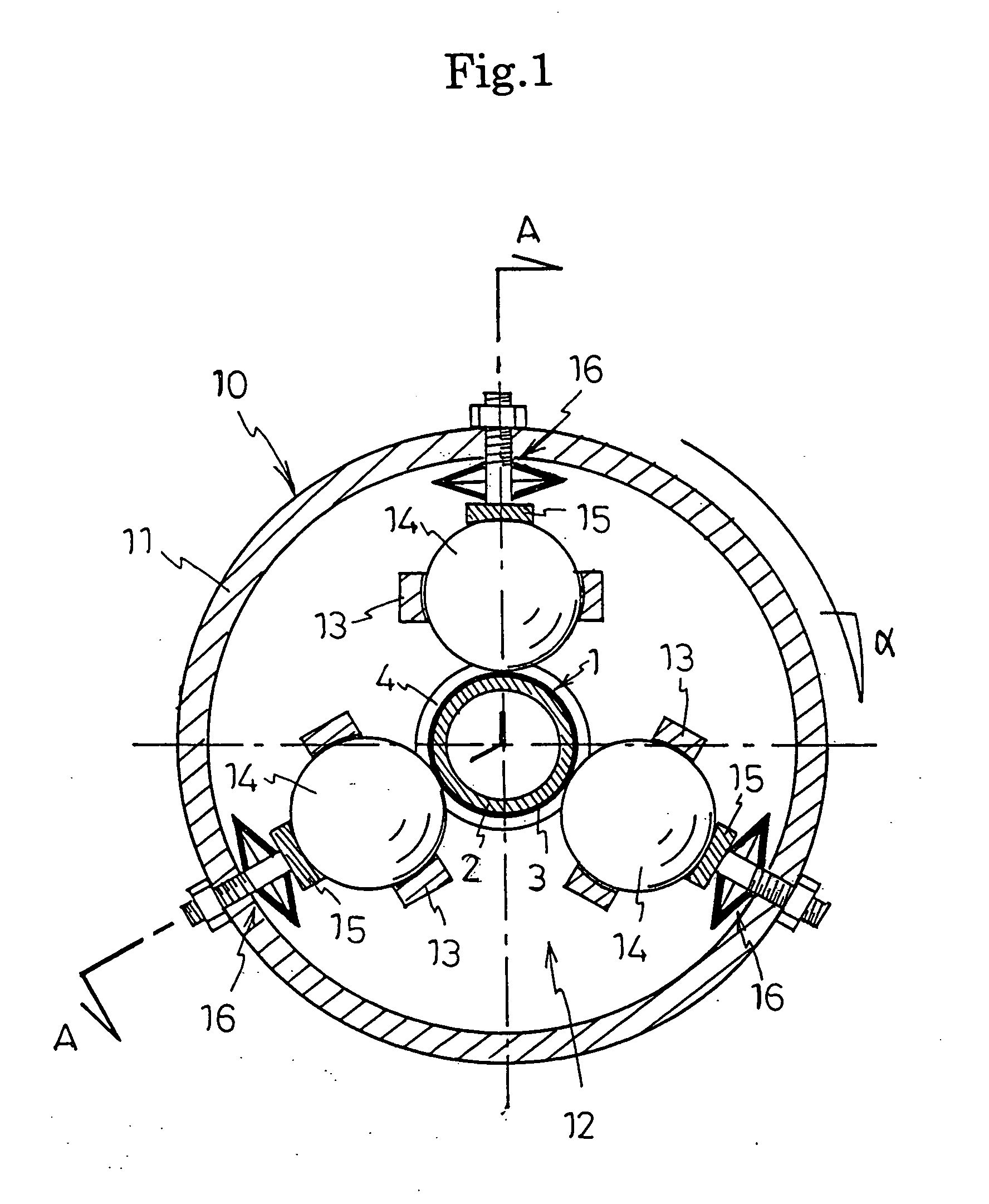
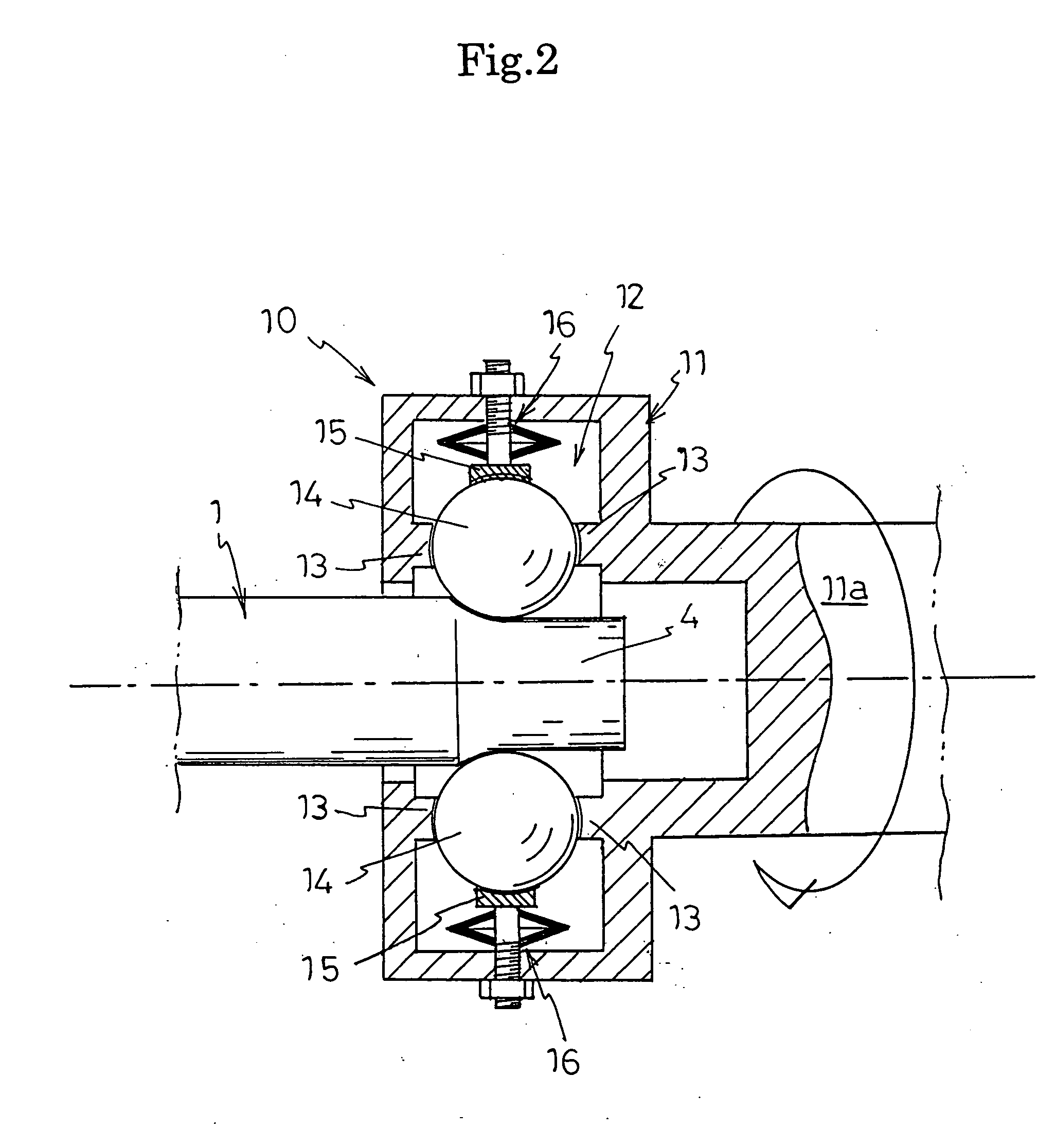
[0018]FIG. 1 is a conceptual cross-sectional front view diagram showing a ball-type stripping apparatus for carrying out the method of removing a coating resin layer of a resin-coated metal tube relating to the present invention, FIG. 2 is a cross-sectional diagram of a portion along line A-A in FIG. 1, and FIG. 3 is a laser apparatus for carrying the method of removing a coating resin layer of a resin-coated metal tube relating to the present invention.

[0019]In the method of removing a coating resin layer of a resin-coated metal tube according to this embodiment, a ball-type stripping apparatus 10 is used as a rotating body and a carbon dioxide gas laser apparatus 20 is used as a laser apparatus.

[0020]Furthermore, the resin-coated metal tube 1 according to this embodiment is formed...


PUM

PropertyMeasurementUnit
thicknessaaaaaaaaaa
surface roughnessaaaaaaaaaa
speedaaaaaaaaaa

Abstract

The present invention provides a method of removing a coated resin layer of a resin-coated metal tube whereby a resin layer can be stripped rapidly without the risk of damaging a plating layer. In a method of removing a coating resin layer of a resin-coated metal tube according to the present invention, a coating resin layer is removed by a rotating body of a rotating body stripping apparatus, whereupon the coating resin layer is removed by a laser beam of a laser apparatus.

Description

BACKGROUND OF THE INVENTION[0001]1. Field of the Invention[0002]The present invention relates to a method of removing a coating resin layer of a resin-coated metal tube.[0003]2. Description of the Related Art[0004]In fuel pipes, and the like, in order to prevent corrosion and provide shock resistance and chemical resistance, and the like, a metal plating such as zinc-aluminum plating is provided on the outer circumferential surface of a metal tube and a resin layer of polyamide resin, or the like, is formed by extrusion molding, or the like, onto the outer circumferential surface of the tube.[0005]When processing the terminations of a resin-coated metal tube such as that described above, it is necessary to remove the outer resin coating layer previously. As methods for removing a resin coating layer of this kind, there is a method according to which a roll is pressed against the coating resin layer of a resin-coated metal tube and the roll is caused to rotate, thereby removing the c...

Claims


Application Information

Patent Timeline
27 May 2010
Publication
US20100126972A1
IPC
B23K26/38; B23K26/00; B23K26/36; B32B43/00
CPC
B23K26/4065; B23K26/365; F02M61/168; F16L19/028; F02M2200/8069; B23K26/361; B23K2103/42; B23K2103/50
Inventors
KON, TAKANORI; TABAYASHI, YOSHIHIDE