Method and Apparatus for Multibarrier Plasma Actuated High Performance Flow Control

a multi-barrier plasma and flow control technology, applied in the direction of air-flow influencers, machines/engines, transportation and packaging, etc., can solve the problems of high power consumption, inability to control flow, and inability to achieve high-performance flow control, and achieve the effect of promoting flow in the flow region and high-performance flow control

Active Publication Date: 2010-05-27
UNIV OF FLORIDA RES FOUNDATION INC
View PDF2 Cites 50 Cited by
  • Summary
  • Abstract
  • Description
  • Claims
  • Application Information

AI Technical Summary

Benefits of technology

[0010]Embodiments of the invention relate to a method and apparatus for plasma actuated high performance flow control. A specific embodiment of a plasma actuator can incorporate a power source; a first electrode in contact with a first dielectric layer and connected to the power source; a second electrode in contact with a second dielectric layer and connected to the power source; and a ground electrode. The power source drives the first electrode with a first ac voltage pattern with respect to the ground electrode and drives the second electrode with a second ac voltage pattern with respect to the ground electrode such that application of the first voltage pattern produces a first plasma discharge in a flow region, and a first electric field pattern in the flow region, and application of the second voltage pattern produces a second plasma discharge in the flow region and a second electric field pattern in the flow region. The first and second electrodes are offset along the direction of flow in the flow region and the first voltage pattern and the second voltage pattern have a phase difference such that the first and se

Problems solved by technology

Under such off-design conditions, separation can occur and performance may be impaired.
However, that requires considerable power and an expensive power supply.
Thus, the illustrated design requires a kHz RF power supply and can arc, making the discharge unstable.
These actuators operate at reasonable power consumption levels at lower speeds but l

Method used


Image

  • Method and Apparatus for Multibarrier Plasma Actuated High Performance Flow Control
  • Method and Apparatus for Multibarrier Plasma Actuated High Performance Flow Control
  • Method and Apparatus for Multibarrier Plasma Actuated High Performance Flow Control

Examples


Embodiment Construction

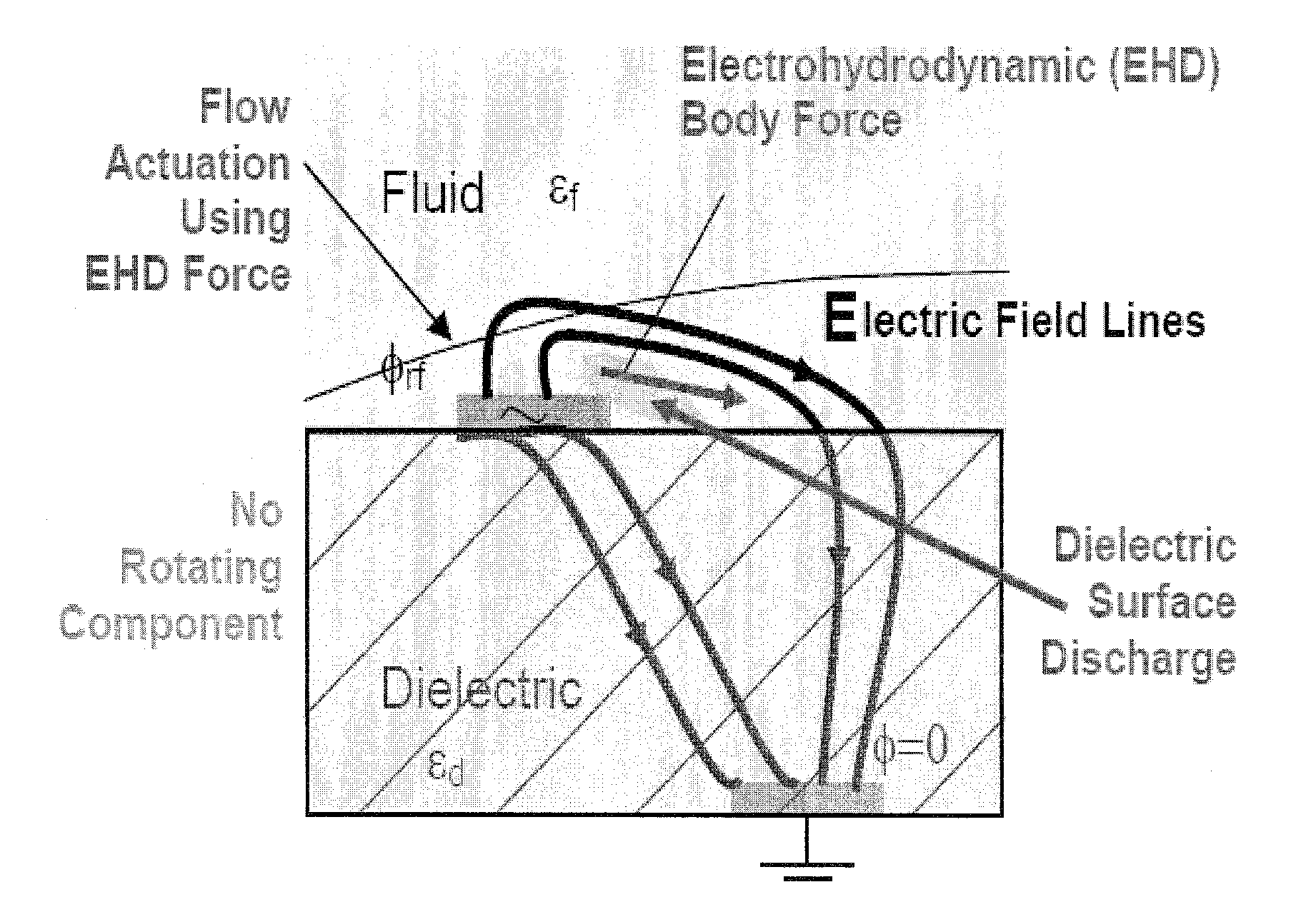
[0035]Embodiments of the invention relate to a method and apparatus for multibarrier plasma actuated high performance flow control. A specific embodiment pertains to a plasma actuator design that results in a dramatic increase in induced velocity at a power consumption level similar to that of a standard monolayer plasma actuator design. In one embodiment, a plasma actuator design of the present disclosure involves a multilayer arrangement of dielectric barriers between sets of electrodes. In a specific embodiment, a multilayer actuator is particularly suitable for flow control in moderate to high speed applications, including those in the aerospace and automotive industries.

[0036]Embodiments are directed to the use of a multilayer or multibarrier plasma actuator design having several layers of a dielectric substrate, each layer enveloping an electrode. In one embodiment, the inter-electrode gap is kept at a few microns to decrease the power requirement. Various configurations inclu...


PUM


Abstract

Embodiments of the invention relate to a method and apparatus for plasma actuated high performance flow control. A specific embodiment of a plasma actuator can incorporate a power source; a first electrode in contact with a first dielectric layer and connected to the power source; a second electrode in contact with a second dielectric layer and connected to the power source; and a ground electrode. The power source drives the first electrode with a first ac voltage pattern with respect to the ground electrode and drives the second electrode with a second ac voltage pattern with respect to the ground electrode such that application of the first voltage pattern produces a first plasma discharge in a flow region, and a first electric field pattern in the flow region, and application of the second voltage pattern produces a second plasma discharge in the flow region and a second electric field pattern in the flow region. The first and second electrodes are offset along the direction of flow in the flow region and the first voltage pattern and the second voltage pattern have a phase difference such that the first and second electric fields drive flow in the flow region in different portions of the flow region at different times.

Description

CROSS-REFERENCE TO RELATED APPLICATION[0001]The present application claims the benefit of U.S. Application Ser. No. 60 / 928,207, filed May 8, 2007, which is hereby incorporated by reference herein in its entirety, including any figures, tables, or drawings.[0002]The subject invention was made with government support under a research project supported by AFOSR Grant Nos. FA9550-05-1-0074 and FA9550-07-1-0131.BACKGROUND OF THE INVENTION[0003]Active flow control is useful for various applications. For example, in propulsion, low-pressure turbines use highly loaded airfoils to improve efficiency and to reduce the number of blades required. The boundary layers, which are fully turbulent at take off, become transitional at high altitudes because of the change in operating environment at cruise. Under such off-design conditions, separation can occur and performance may be impaired. Similarly, in external aerodynamics, the maximum lift and stall characteristics of a wing affect take off and ...

Claims


Application Information

Patent Timeline
IPC IPC(8): H05H1/24
CPCB64C23/005F05D2270/172B64C2230/12H05H1/24Y02T50/166F15D1/12H05H1/2406Y10T137/218Y02T50/10H05H1/2425H05H1/2418
Inventor ROY, SUBRATA
Owner UNIV OF FLORIDA RES FOUNDATION INC
Why Eureka
Try Eureka