Phase current estimation device of motor and magnetic pole position estimation device of motor

a technology of phase current estimation and motor, which is applied in the direction of motor/generator/converter stopper, electronic commutator, dynamo-electric converter control, etc., can solve the problems of decreasing the stability of controlling current, and increasing noise and torque, so as to achieve the effect of preventing the modulation factor of the inverter and more accuracy

Inactive Publication Date: 2010-05-27
HONDA MOTOR CO LTD
View PDF11 Cites 24 Cited by
  • Summary
  • Abstract
  • Description
  • Claims
  • Application Information

AI Technical Summary

Benefits of technology

[0013]Based on the phase current estimation device of the motor described above in (2), a feedback control is performed on the current during a startup control so that the deviation between the γ-axis current command value and the γ-axis current detection value becomes zero. Thus, until the rotational velocity of the motor reaches a value such that a self control can be performed, the modulation factor of the inverter can be prevented from dropping below a predetermined lower limit of the modulation factor. In this way, it is possible to retain a predetermined pulse width (in other words, the pulse width of the pulse width modulation) that is necessary to appropriately detect the DC side current when the phase current is estimated from the DC side current of the inverter. Consequently, the phase current can be estimated with more accuracy.

Problems solved by technology

When the command voltage vector is broken up into two vectors in this way, a harmonic component (the difference between the command voltage vector and the vector obtained by breaking up the command voltage vector) is created, which triggers an increase in noise and torque pulsation.
Thus, there is a problem in that the stability of controlling the current declines.
As a result, a harmonic component occurs, triggering a decrease in the stability of controlling the current.
Thus, when the phase current is estimated from the DC side current of the inverter during a sensor-less control, for example, it becomes difficult to retain a predetermined pulse width (in other words, the pulse width of the pulse width modulation) that is necessary to appropriately detect the DC side current.
Furthermore, there is also a problem in that the region with a small modulation factor expands as the input voltage of the inverter increases.

Method used


Image

  • Phase current estimation device of motor and magnetic pole position estimation device of motor
  • Phase current estimation device of motor and magnetic pole position estimation device of motor
  • Phase current estimation device of motor and magnetic pole position estimation device of motor

Examples


Embodiment Construction

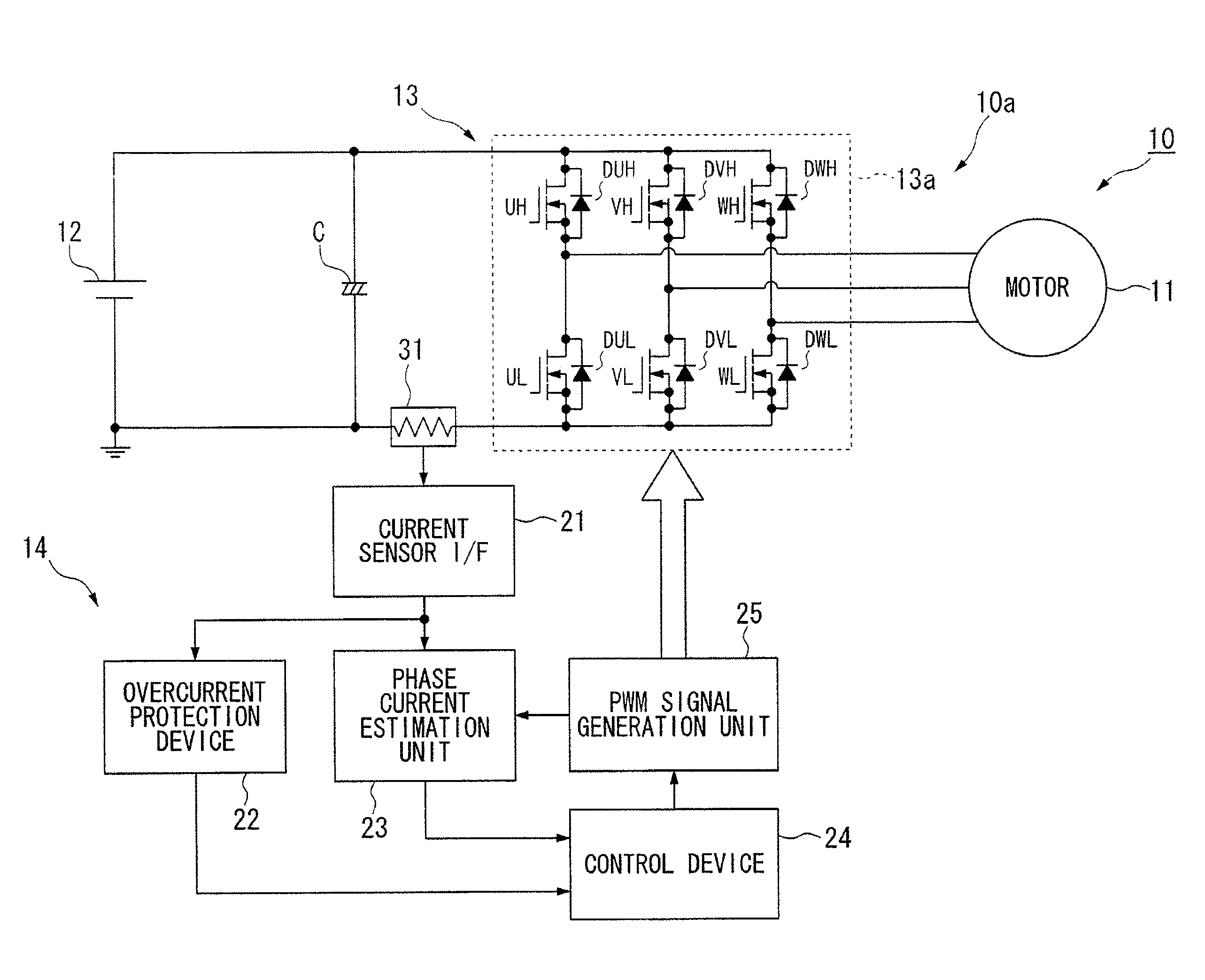
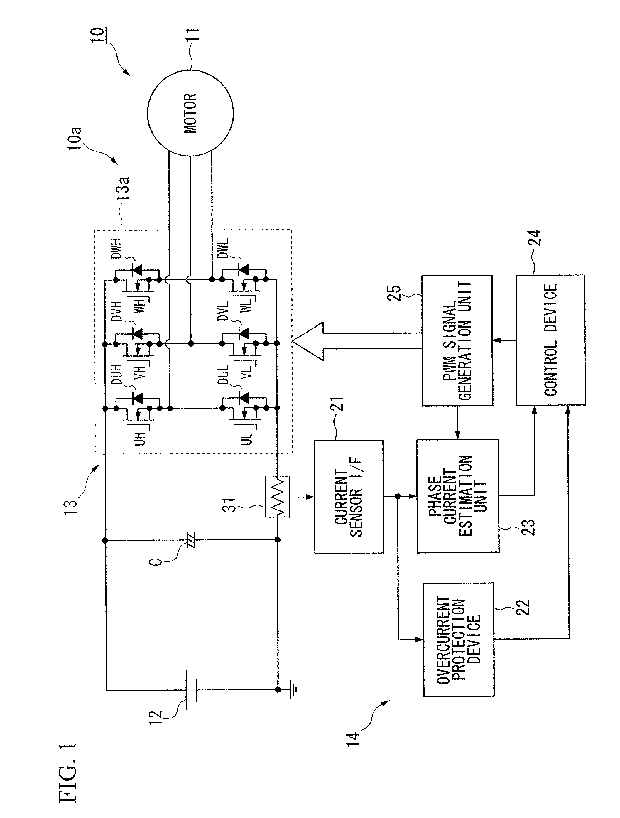
[0032]Hereinafter, a first embodiment of a phase current estimation device of a motor and a magnetic pole position estimation device of a motor according to an aspect of the present invention is described, with reference to FIGS. 1 to 9.

[0033]A phase current estimation device 10a of a motor (hereinafter, simply referred to as a phase current estimation device 10a) according to the above embodiment is provided in a magnetic pole position estimation device 10 of a motor (hereinafter, simply referred to as a magnetic pole position estimation device 10). The phase current estimation device 10a estimates each phase current flowing through a brushless DC motor 11 of a three-phase alternate current (hereinafter, simply referred to as a motor 11). This motor 11 includes a rotator (not diagramed) and a stator (not diagramed). The rotator includes a permanent magnet used as a magnetic field. The stator generates a rotating magnetic field that rotates this rotator. The magnetic pole position e...


PUM


Abstract

A phase current estimation device of a motor includes: an inverter which uses a pulse width modulation signal to sequentially commutate an electric flow to a motor of a three-phase alternating current; a pulse width modulation signal generation unit generating the pulse width modulation signal from a carrier signal; a control unit performing a startup control and a self control of the motor using the inverter; a direct current sensor detecting a direct current of the inverter; and a phase current estimation unit estimating a phase current based on the direct current detected by the direct current sensor.

Description

BACKGROUND OF THE INVENTION[0001]The present application claims priority on Japanese Patent Application No. 2008-300927, filed Nov. 26, 2008, the content of which is incorporated herein by reference.FIELD OF THE INVENTION[0002]The present invention relates to a phase current estimation device of a motor and a magnetic pole position estimation device of a motor.DESCRIPTION OF THE RELATED ART[0003]A conventionally known inverter device obtains a predetermined pulse width when the modulation degree is small or when the phase of the output voltage vector is close to the phase of a single basic voltage vector. This conventionally known inverter device outputs the vector components of a first basic voltage vector and a second basic voltage vector within a first time period. The first and second basic voltage vectors can create a command voltage vector. The phases of these first and second basic voltage vectors differ by sixty degrees. The first time period is equal to one PWM cycle (one t...

Claims


Application Information

Patent Timeline
Patent Type & Authority Applications(United States)
IPC IPC(8): H02P6/18H02P6/20H02P6/06H02P6/16H02P6/08H02P6/17H02P6/28H02P21/00H02P21/05H02P21/18H02P21/22H02P21/24H02P21/28H02P23/04H02P25/026H02P27/04H02P27/08
CPCH02P21/0032H02P21/0039H02P2203/05H02P27/08H02P21/14H02P21/34H02P21/24
Inventor AKIYAMA, MASAHIKO
Owner HONDA MOTOR CO LTD
Why Eureka
Try Eureka