Control device and control method for electric system

Active Publication Date: 2010-05-27
TOYOTA JIDOSHA KK +1
View PDF4 Cites 15 Cited by
  • Summary
  • Abstract
  • Description
  • Claims
  • Application Information

AI Technical Summary

Benefits of technology

[0019]According to this configuration, the first power storage mechanism and the second power storage mechanism are charged simultaneously in different

Problems solved by technology

When a plurality of power storage mechanisms are mounted on the vehicle, however, charging conditions of all the power storage mechanisms may not necessarily be equal.
For example, sufficiently charged power storage mechanisms and insufficiently charged power storage mechanisms may both be present, so that states of char

Method used


Image

  • Control device and control method for electric system
  • Control device and control method for electric system
  • Control device and control method for electric system

Examples


Embodiment Construction

[0030]An embodiment of the present invention will be described hereinafter with reference to the drawings. In the following description, the same components are designated with the same characters. Their names and functions are also the same. Accordingly, detailed descriptions thereof will not be repeated.

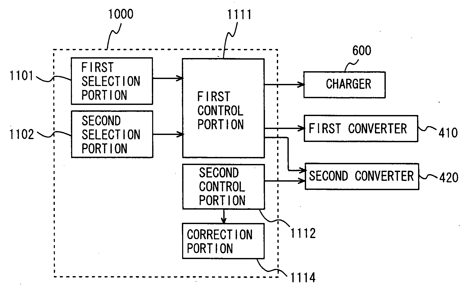
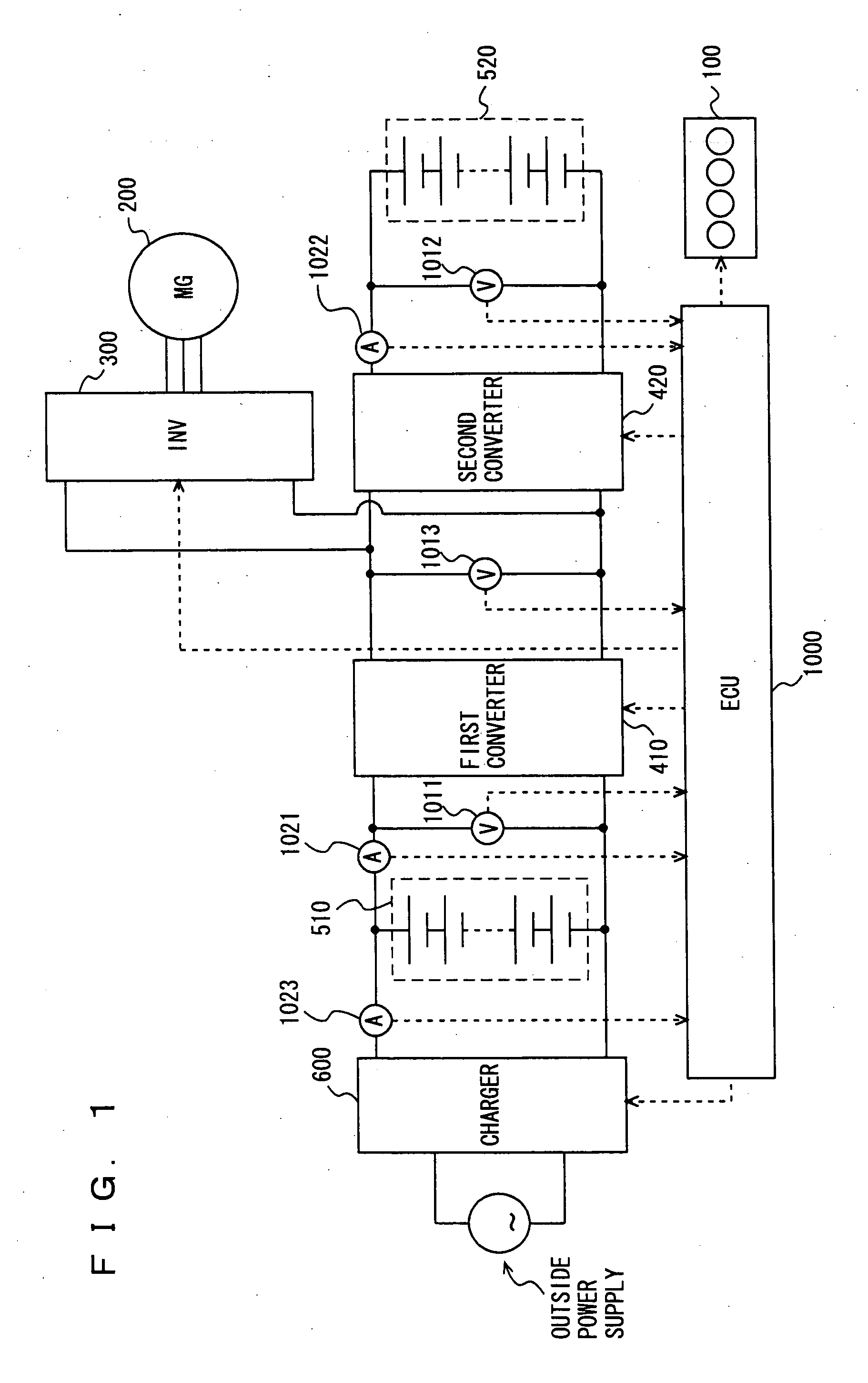
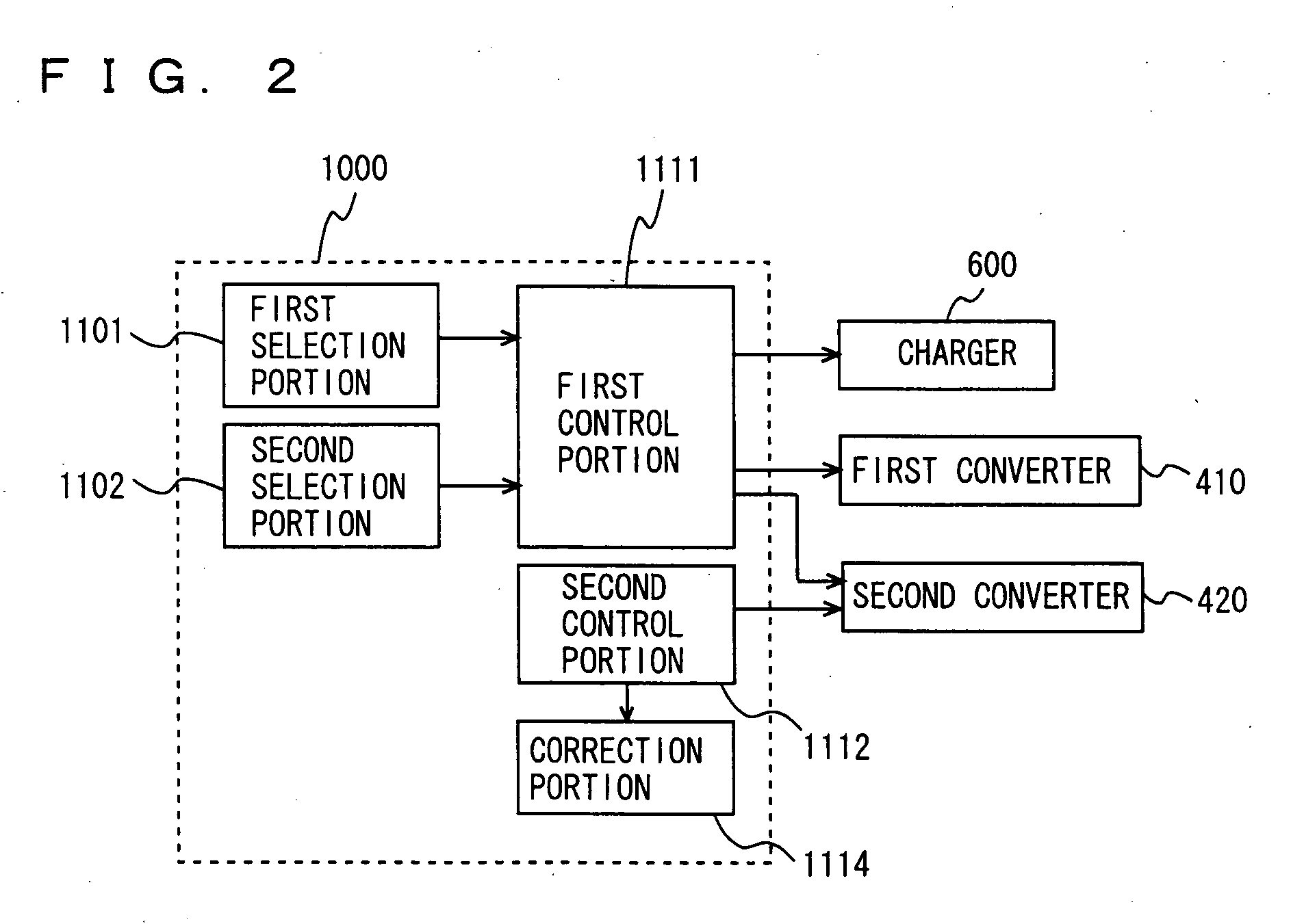
[0031]Referring to FIG. 1, a hybrid vehicle having a control device for an electric system according to the present embodiment will be described. This hybrid vehicle has an engine 100, an MG (Motor Generator) 200, an inverter 300, a first converter 410, a second converter 420, a first battery pack 510, a second battery pack 520, a charger 600, and an ECU (Electronic Control Unit) 1000. It is noted that ECU 1000 may be divided into a plurality of ECUs.

[0032]The electric system includes MG 200, inverter 300, first converter 410, second converter 420, first battery pack 510, second battery pack 520, and charger 600. The hybrid vehicle runs by driving force from at least any one of eng...


PUM


Abstract

In an electric system including a first converter and a second converter connected in parallel, an ECU executes a program including a step of selecting a charging mode for a first battery pack connected to the first converter and a charging mode for a second battery pack connected to the second converter, and a step of controlling a charger connected to the first battery pack, the first converter and the second converter to charge the first battery pack and the second battery pack in the selected charging modes.

Description

TECHNICAL FIELD[0001]The present invention relates to a control device and a control method for an electric system, and more particularly to a technique of charging each power storage mechanism in an individually set mode.BACKGROUND ART[0002]Conventionally, hybrid vehicles, electric vehicles and the like have been known that run by driving force of an electric motor. These vehicles have a battery mounted thereon for storing electric power to be supplied to the electric motor serving as a driving source.[0003]Japanese Patent Laying-Open No. 8-37703 discloses a hybrid electric vehicle including a battery charged by an outside charger, a driving motor for driving wheels by electric power from the battery, an engine used indirectly for driving the wheels, a control unit for controlling operations of the motor and of the engine, and a determination unit for determining whether the battery meets prescribed specifications. When means for determining battery specifications determines that t...

Claims


Application Information

Patent Timeline
IPC IPC(8): H02J7/04H02J7/00B60L50/16H02J7/02
CPCB60L11/1861B60L11/1868H01M10/441H02J7/0018Y02T10/7066Y02T10/7005Y02T10/7044Y02T10/7055H02J7/0019B60L58/12B60L58/20Y02T10/70Y02E60/10
Inventor IIDA, TAKAHIDE
Owner TOYOTA JIDOSHA KK
Why Eureka
Try Eureka