Image forming device, image forming method and storage medium

Active Publication Date: 2010-05-27
CANON KK
View PDF4 Cites 11 Cited by
  • Summary
  • Abstract
  • Description
  • Claims
  • Application Information

AI Technical Summary

Benefits of technology

[0019]According to the present invention, in correcting a curve or an inclination of a scan line in a laser scan device, it is possible to realize correction processing which reduces unstable intermediate dots to be generated as compared to PWM or light volume

Problems solved by technology

One of the factors is unevenness or a mounting position shift of a lens in a deflection scan device and a mounting position shift of the deflection scan device to a color image forming device body.
In this method, since the registration shift is electrically corrected by processing the image data, a mechanical adjustment member or an adjustment process on assembly becomes unnecessary.
Therefore, an image in which the density is expressed with roughness and closeness of a microdot, for example, one dot results in

Method used


Image

  • Image forming device, image forming method and storage medium
  • Image forming device, image forming method and storage medium
  • Image forming device, image forming method and storage medium

Examples


embodiment 1

[0039]FIG. 4 is a diagram explaining each block relating to electrostatic latent image production in a color image forming device of an electronic photograph system according to Embodiment 1. The color image forming device includes an image forming unit 401 and an image processing unit 402, wherein the image processing unit 402 generates bit map image information and the image forming unit 401 performs image formation onto a print medium based upon the bit map image information.

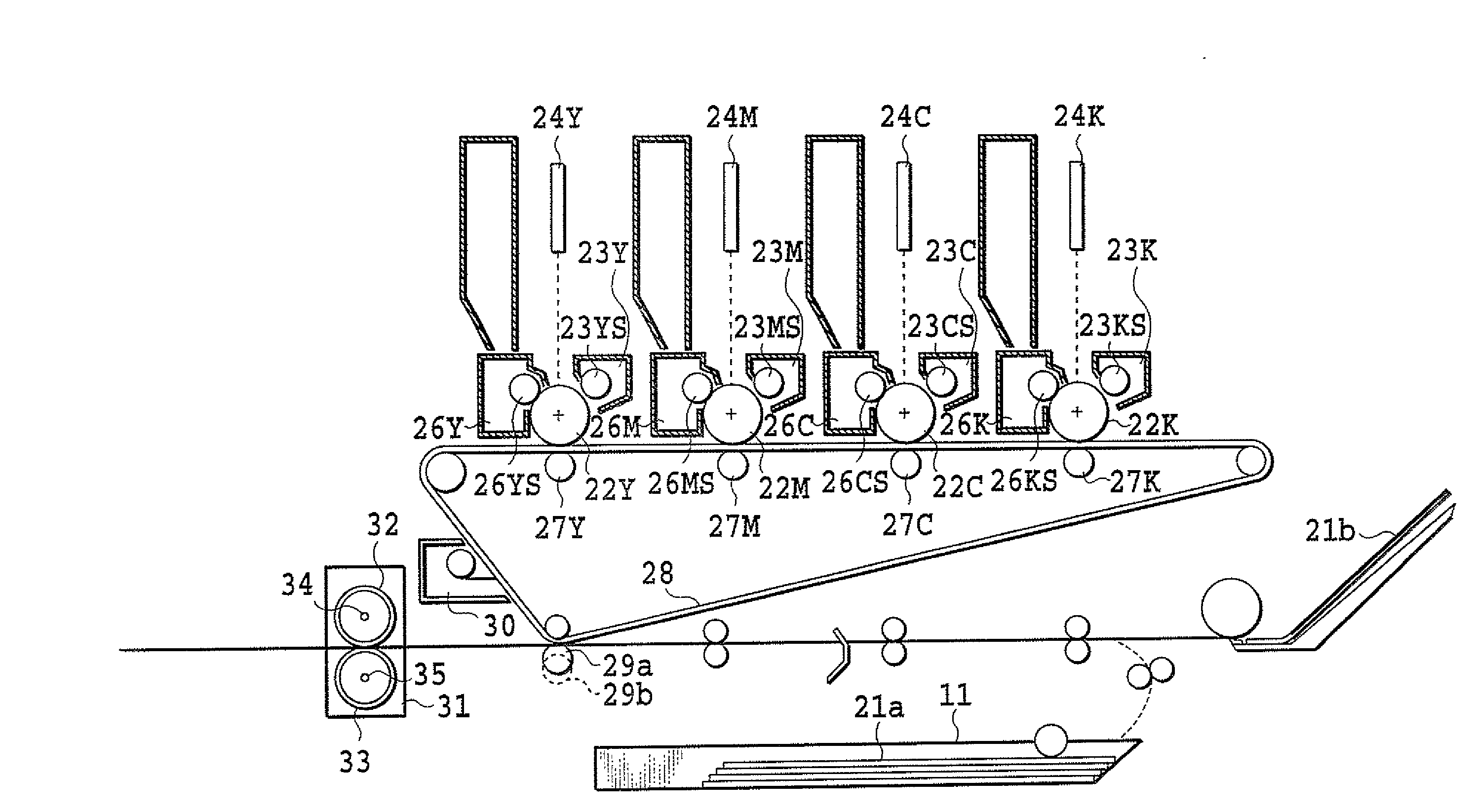
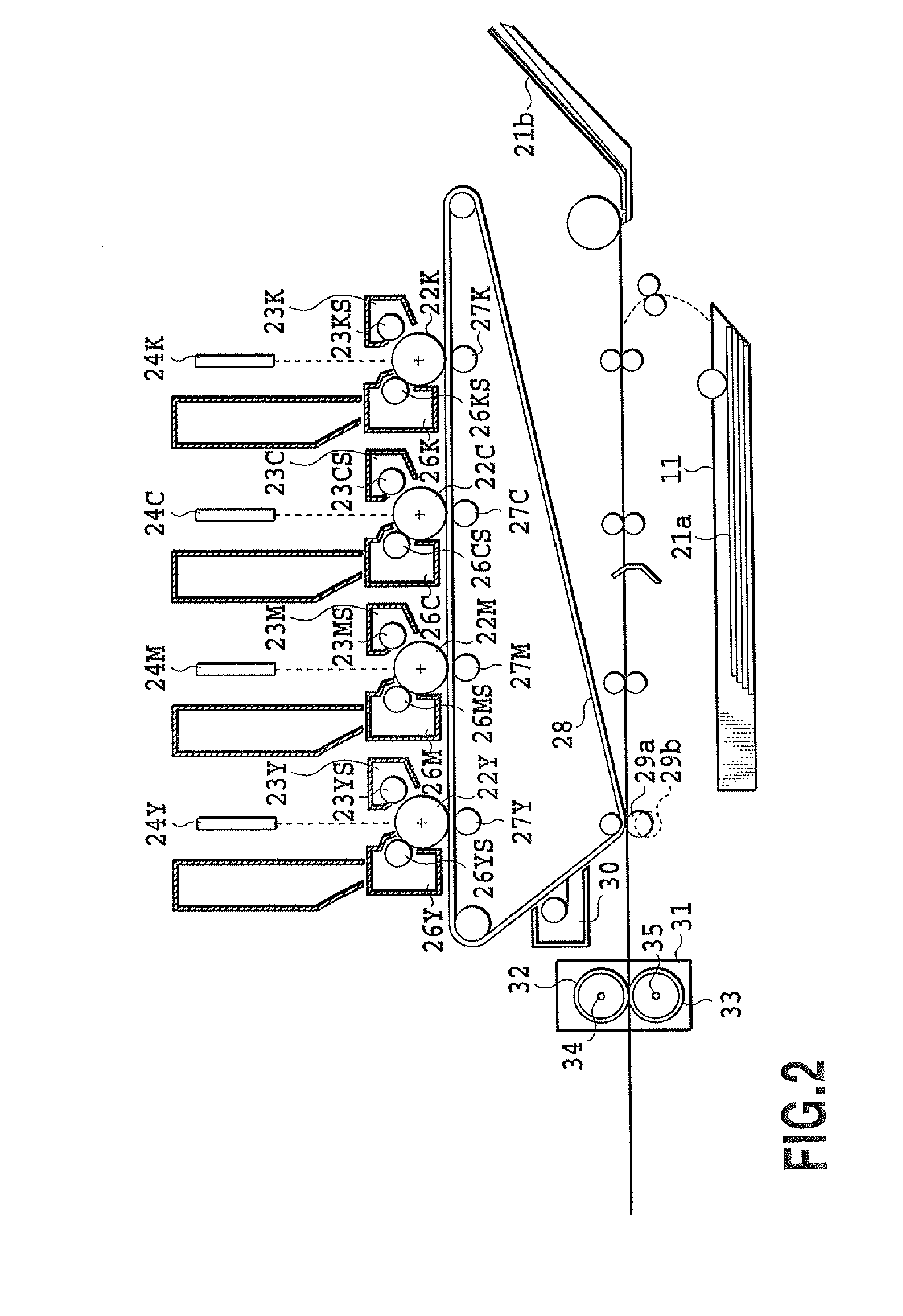
[0040]FIG. 2 is a cross section of a color image forming device of a tandem system adopting an intermediate transfer body 28 as one example of the color image forming device of the electronic photograph system. By referring to FIG. 4, there will be explained an operation of the image forming unit 401 in the color image forming device of the electronic photograph system.

[0041]The image forming unit 401 drives exposure light in accordance with an exposure time processed at the image processing unit 402 to form ...

embodiment 2

[0089]As described above, the half tone processing units 407 (407C, 407M, 407Y, and 407K) execute the half tone processing to the attribute data and the data of the respective colors outputted from the memory unit 406. A specific example of the half tone processing includes screen processing or error dispersion processing.

[0090]The screen processing executes N-value processing of input image data using predetermined plural matrixes.

[0091]In addition, the error dispersion processing executes N-value processing by comparing the input image data with a predetermined threshold value to disperse a difference between the input image data and the output image data at that point to the peripheral pixels which are subject to N-value processing subsequently.

[0092]In a case of forming a half tone image by the error dispersion processing, the processing including the random number is usually executed at the time of expressing an intermediate tone and the density is expressed at a random pattern...

embodiment 3

[0099]In the Embodiment 1 and Embodiment 2, if the main scan direction is the same, the same shift processing is executed in the sub scan direction without fail, but in Embodiment 3, the shift position is changed for each sub scan. As described in Embodiment 1, when the upper and lower lines are referred to by using the remainder of the main scan pixel position, the same reference relation is made in the same main scan position without fail. In consequence, the line is uniformly shifted in the sub scan direction. Therefore, the uniformity is disrupted by providing random components thereto to weaken the visibility as a streak.

[0100]More specially the disturbance is applied to the remainder of the main scan pixel position described in Embodiment 1. Here, in considering the timing of applying the disturbance, when the disturbance is applied uniformly to all pixels, the density can not be possibly stored before or after the interpolation. Therefore, the disturbance is generated only on...


PUM


Abstract

A problem of the present invention is to provide an image forming device which can minimize density unevenness due to interpolation processing. For solving the above problem, an image forming device according to the present invention is an image forming device including printing unit for printing an image by scanning a photosensitive body comprising correcting unit for correcting a position in which the image is printed, wherein the correcting unit outputs one of a data of a line of interest, a data of a line adjacent to the line of interest, and a data of an intermediate value between the line of interest and the line adjacent to the line of interest in accordance with a pixel shift amount and a main scan pixel position, and the printing unit scans the photosensitive body based upon the outputted data.

Description

BACKGROUND OF THE INVENTION[0001]1. Field of the Invention[0002]The present invention relates to an image forming device, an image forming method and a storage medium.[0003]2. Description of the Related Art[0004]An electronic photograph system is known as an image printing system used in a color image forming device such as a color printer or a color copying machine. The electro photograph system is designed to form a latent image on a photosensitive drum using a laser beam and develop the latent image by a charged color material (hereinafter, refer to a toner). Printing of an image is carried out by transferring and fixing the developed image by the toner onto a transfer paper.[0005]In recent years, a color image forming device of a tandem system has been increasing, which is provided with developing machines and photosensitive drums each number of which is the same as the color number of the toner for achieving a high speed in image forming and sequentially transfers images in dif...

Claims


Application Information

Patent Timeline
IPC IPC(8): G06K15/00
CPCG03G2221/1684G03G21/1853
Inventor TAMURA, HIROKAZU
Owner CANON KK
Why Eureka
Try Eureka