Wiper member for a container for packaging and dispensing products

a technology for cosmetics or care products and wipers, which is applied in the direction of packaging foodstuffs, transportation and packaging, and packaged goods types. it can solve the problems of not stopping users from continuing, the applicator stem being prone to jump out of the container, and the wiper not being able to fit into narrow necked containers. , to achieve the effect of preventing the product from drying out and increasing the product li

Inactive Publication Date: 2010-05-27
ZEN DESIGN SOLUTIONS
View PDF11 Cites 11 Cited by
  • Summary
  • Abstract
  • Description
  • Claims
  • Application Information

AI Technical Summary

Benefits of technology

[0017]The present invention generally is a wiper for a container for packaging and dispensing cosmetic or care products. More particularly, the invention relates to a wiper member that is novel and inventive by way of its construction such that it prevents air from getting pumped / entrapped inside the container during usage. There is provided a wiper member that helps in increasing the life of the product by allowing it to remain in its original fluid state and prevents drying out of the product. Further, the wiper member by virtue of its internal configuration results in efficient wiping of the applicator element and at the same time provides an anti-pumping action by allowing the air to pass through the air vents in it.

Problems solved by technology

Furthermore, the addition of air in the bulk causes the product to become lumpy and may also lead to infection by bacteria.
However, this has not stopped the users from continuing with the pumping actions which is a more natural and psychologically satisfying response when trying to churn or mix the bulk.
Although, the pumped air causes the applicator stem to have a tendency to jump out of the container as soon as the cap is unscrewed.
However, this wiper might not be able to fit onto narrow necked containers as the extended holes would need a certain area to be able to function as vent creating holes.
However, the disclosed wiper has a problem that there are gaps created in the wiping zone which results in appearance of product streaks on the applicator rod even after being wiped.
Further, the slits in the wiper may lead to a decrease in the efficiency of the wiper with regular usage.
However, in aforementioned volume control wipers, there is an external body being used to cause constriction or relaxation of wiper to control the aperture diameter.
Further, the as the wiper makes physical contact with the rigid external body, there are chances that the product might get clogged at such spaces.
Also, most of the existing devices are typically complex in construction and costly to manufacture.
Further, such devices are often ineffective in removing excess mascara from the applicator.
As a result, the consumer is still often required, in an additional step, to manually remove excess mascara from the applicator using a tissue or other similar item.
As can be appreciated, this additional step renders the entire mascara application process more time consuming and results in a greater waste of mascara.
Further, these wipers are not able to provide a simultaneous anti-pumping action.
The wiper is fixed inside the neck of the container and when a force is applied or removed from its central axis, the wiper gets either constricted thereby causing the flange-like projections to come close together and cause maximum interference with the applicator element which in turn results in close wiping of the applicator and lesser product is available for application.
Further, there is no additional component inserted or withdrawn to achieve the deformation in the wiper.

Method used


Image

  • Wiper member for a container for packaging and dispensing products
  • Wiper member for a container for packaging and dispensing products
  • Wiper member for a container for packaging and dispensing products

Examples


Embodiment Construction

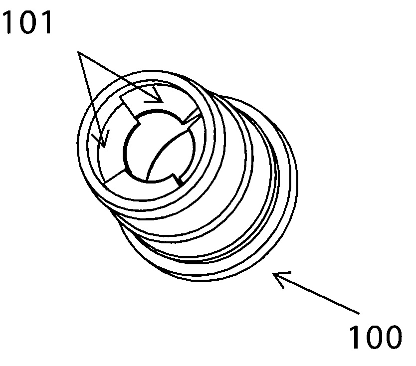
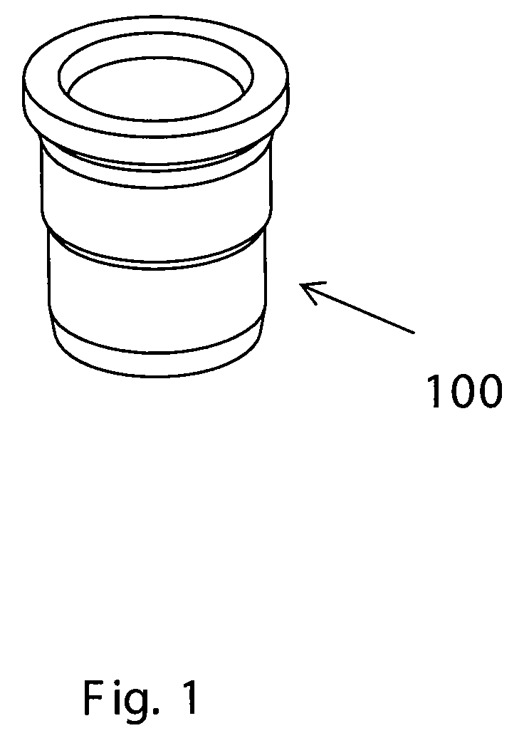
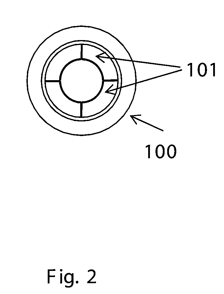
[0047]The wiper member of a container according to one embodiment of the present invention is shown in FIGS. 1 to 4.

[0048]FIG. 1 is one embodiment of the present invention showing the wiper member 100. As represented by FIGS. 2 and 3, there are present flange-like projections 101 on the inner diameter of the wiper member 100. FIG. 4 illustrates an align section view of the wiper member 100 wherein it is visible that the flange-like projections 101 are placed at varying heights inside the wiper. Further, there are more than one flange-like projections 101 present in the wiper member 100.

[0049]FIGS. 5 to 7 represent the wiper member 200 according to yet another embodiment of the invention. As can be seen from these figures, there are present two flange-like projections 201 and 202 inside the wiper member 200 and one of the projections 201 occupies a larger proportion than the other flange-like projection 202. Further, these projections are placed at varying heights inside the wiper. H...


PUM


Abstract

The present invention generally is a wiper for a container for dispensing and dispensing cosmetic or care products. More particularly, the invention relates to a wiper member that is novel and inventive by way of its construction such that it prevents air from getting pumped/entrapped inside the container during usage. There is provided a wiper member that helps in increasing the life of the product by allowing it to remain in its original fluid state and prevents drying out of the product. Further, the wiper member by virtue of its internal configuration results in efficient wiping of the applicator element and at the same time provides an anti-pumping action by allowing the air to pass through the air vents in it. Also disclosed is a wiper member that is able to regulate the amount of product retained on the applicator when a force is either applied or removed from its central axis.

Description

BACKGROUND[0001]1. Field of the Invention[0002]Embodiments of the present invention generally relate to a wiper member for a container for packaging and dispensing cosmetics or care products. More particularly the invention relates to a wiper member that provides for an anti-pumping action to take place when the container is put to use and also provides for a product with a longer life. The present invention also relates to the wiper member being able to provide varying amounts of product to be retained on the applicator as per user's convenience for application of a cosmetic or a care product.[0003]Wiper member of the present invention can be employed in application of various products, such as for viscous cosmetics, mascara, eye liner, lip gloss, coloring strands of hair and like products.[0004]2. Description of the Related Art[0005]Numerous kinds of cosmetic and care products are available in the market today. Some such products include mascara, lip gloss, eye liner or like produ...

Claims


Application Information

Patent Timeline
Patent Type & Authority Applications(United States)
IPC IPC(8): A46B17/08
CPCA45D40/267
Inventor PIRES, LEO CLIFFORDHWANG, ROGERBOSE, RAHULSETH, ITIKOHLI, KOUSHIKDESWAL, RAJESHVASHISHTHA, BHAVANA
Owner ZEN DESIGN SOLUTIONS
Why Eureka
Try Eureka