Hybrid riser systems and methods

a riser and hybrid technology, applied in the field of hybrid riser systems and methods, can solve the problems of reducing the fatigue life of the steel catenary riser, the drawback of being heavy and having a high cost, and the cost of the hybrid riser may limit the number of its applications

Active Publication Date: 2010-05-27
SHELL OIL CO
View PDF9 Cites 3 Cited by
  • Summary
  • Abstract
  • Description
  • Claims
  • Application Information

AI Technical Summary

Benefits of technology

[0012]In one aspect, the invention provides a method of modifying a floating system, the system comprising a host floating in a body of water having a water bottom, an elongated underwater structure with a first end, a second end, and a body positioned between the first end and the second end, with the first end connected to the host, the body extending through the water, and the second end adjacent the water bottom, the method comprising disconnecting the first end from the host; connecting the first end to a flotation module; connecting a flexible hose to the flotation module and the host; and maintaining the flotation module at a depth below a surface of the body of water.

Problems solved by technology

However, if the host has significant oscillations, the motion can pass to the riser, especially to the touchdown region, and reduce the fatigue life of the steel catenary riser.
However, it may have the drawbacks of being heavy and having a high cost.
The cost of the hybrid riser may limit the number of its applications.

Method used


Image

  • Hybrid riser systems and methods
  • Hybrid riser systems and methods
  • Hybrid riser systems and methods

Examples


example 1

[0058]A production riser 8.625″ (0.22 m) OD and 1.51″ (0.038 m) wall may be used to deliver oil production to a production offshore platform in 1000-meter water. The load to support a conventional steel catenary riser is about 136 tons, which is beyond the remaining deck load capacity of the platform. If a hybrid riser in FIG. 3 is used, then the deck load is only 41 tons, but requiring a riser base and tiebacks.

[0059]The embodiment illustrated in FIG. 4 would include a 180-meter flexible hose and 140-meters long chain (95 mm OD), and an aircan of 130-ton net buoyancy. Then the deck load may be as small as 36 tons. During normal oil production, the top of the aircan is 72 meters below the water surface. In a pipe empty state, the aircan may rise, but its top is still 41 meters below the sea surface, below the bottom of the passing boats. Other responses, such as stress levels, fatigue life; flexible hose motions, etc. are all satisfied. This configuration may achieve significant cos...

example 2

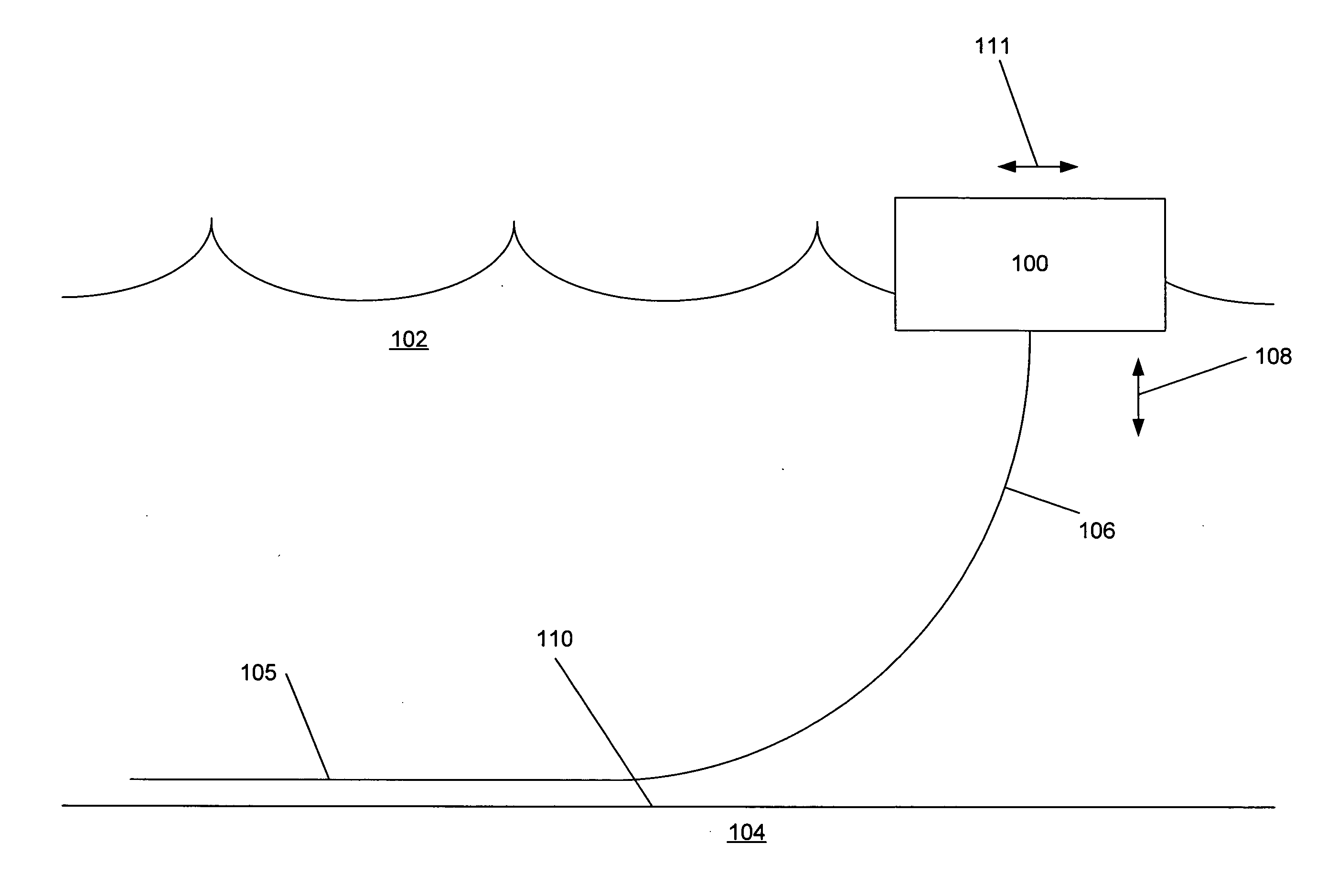
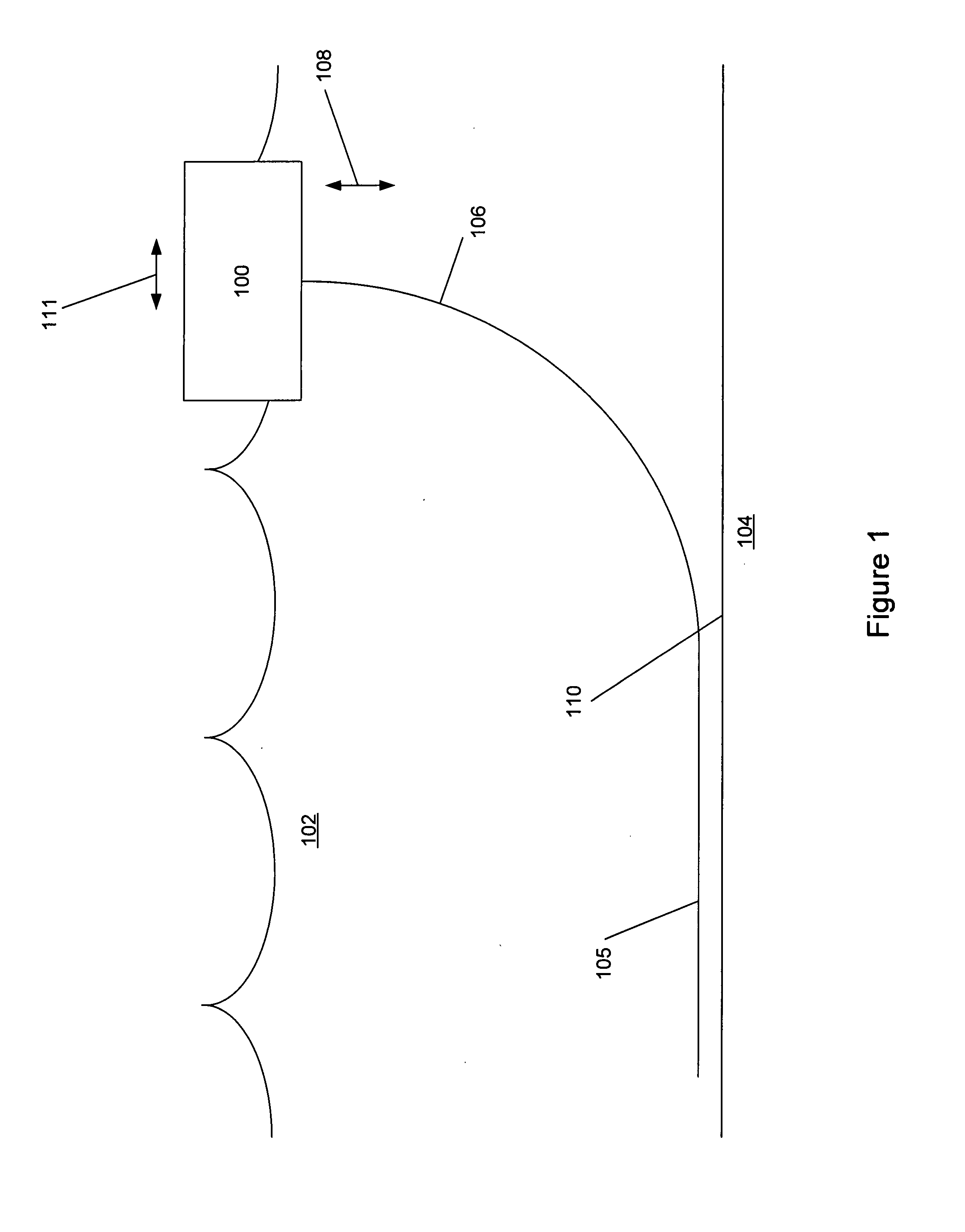
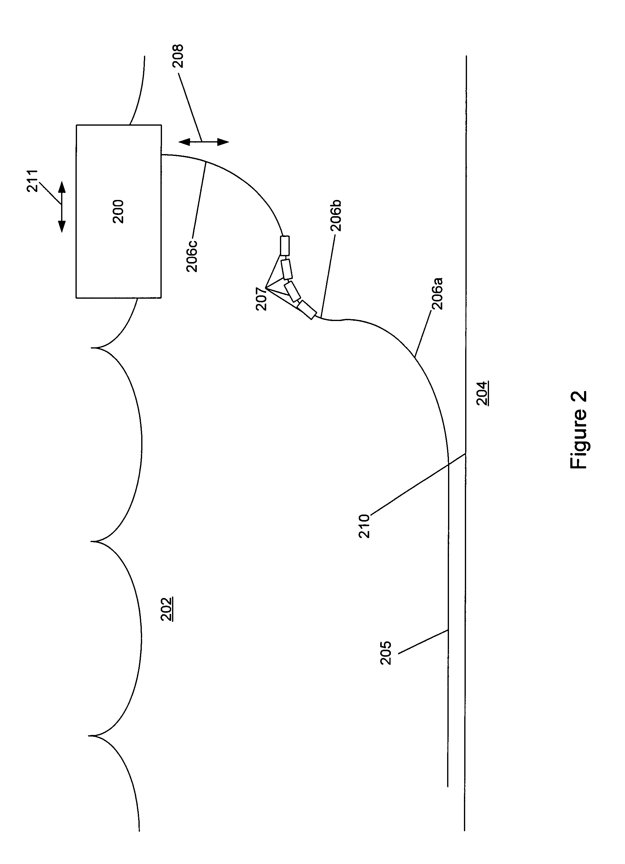
[0060]A production riser 10.75″×0.875″ (0.27×0.022 meters) is required to connect to a turret FPSO in 1760 meter water. The heave oscillations of the turret are so large that the fatigue life of a conventional SCR configuration as shown in FIG. 1 can only last hours at its touchdown region. The lazy wave riser configuration in FIG. 2 can lengthen the fatigue life in the touchdown region, with a sacrifice of fatigue lives of the upper portion and installation difficulty. The hybrid riser described in FIG. 3 can with a high cost, including a foam module of 215 ton net buoyancy, riser base, tiebacks, etc.

[0061]The embodiment illustrated by FIG. 6 may be used, including a 400-meter flexible hose, and an aircan of 190-ton net buoyancy. A pre-bent pipe segment around the anchoring point may be formed during installation. After the anchoring cable is connected, a pull-up on purpose at the riser top forces a short segment of the pipe at the anchoring point to bend permanently (plastically)....


PUM


Abstract

There is disclosed a floating system positioned in a body of water having a water bottom, the system comprising a host member floating on a surface of the water; a flotation module floating under the surface of the water; a flexible hose connecting the host member to the flotation module; and an elongated underwater line structure, comprising a top portion connected to the flotation module; a bottom portion extending to the water bottom and adapted to connect to a flowline lying on the water bottom; and at least one of the top portion and the bottom portion comprising a catenary configuration.

Description

FIELD OF THE INVENTION[0001]The present invention relates to systems of underwater line structures extending from a floating structure at the sea surface to the seabed, and relates to the processes of installing and using such systems.DESCRIPTION OF THE RELATED ART[0002]Several configurations for connecting a floating structure (host) with a seabed pipeline have been proposed. The configurations used depend, in general, on parameters relating to the depth of water and the horizontal and vertical movements of the floating structure in order to select the appropriate configuration and / or the type of connection.[0003]One configuration is the top-tensioned riser, or vertical rigid riser. In this configuration, the riser vertically stands on a foundation at the seabed. Near its top, the riser is pulled upward by a tensioning system (or a buoyancy system) at the floating structure. The tensioning system (or buoyancy system) is designed so that the riser top portion follows the horizontal ...

Claims


Application Information

Patent Timeline
Patent Type & Authority Applications(United States)
IPC IPC(8): B63B21/50E02D29/00E02D15/02
CPCB63B21/50B63B35/44B63B27/24B63B22/04E21B17/015B63B21/00
Inventor RODENBUSCH, GEORGEZHANG, HEPINGZHANG, JANE QING
Owner SHELL OIL CO
Why Eureka
Try Eureka