Modular surface foundation for wind turbine space frame towers

a technology for space frame towers and modules, applied in the field of modules for wind turbine space frame towers, can solve the problems of increasing the overall size of the wind turbine, increasing the foundation requirements, and further increasing the bottom load of the tower, so as to reduce the excavation costs and reduce the installation cost

Inactive Publication Date: 2010-06-03
GENERAL ELECTRIC CO
View PDF6 Cites 33 Cited by
  • Summary
  • Abstract
  • Description
  • Claims
  • Application Information

AI Technical Summary

Benefits of technology

[0009]One advantage of the present disclosure is that the modular surface foundation provides reduced excavation costs and requires less material to install compared to current space frame tower foundations.
[0010]Another advantage of the present disclosure is that the modular surface foundation provides storage for down tower equipment.
[0011]Yet another advantage of the present disclosure is that the modular surface foundation provides additional height to the space frame tower.

Problems solved by technology

As power requirements increase, the size of wind turbine rotor blades increase which causes an increase in the overall size of the wind turbine, resulting in further increases in tower bottom load which also increases the foundation requirements.
The current foundation approaches for space frame towers suffer from various obvious draw-backs.
Although material requirements for the foundations for wind turbine space frame towers are substantially less than that of traditional single steel tube towers, the amount of concrete, rebar and other reinforcements is still costly.
Furthermore, because of the design of traditional wind turbine space frame towers, additional structures must be built on-site to house any necessary down tower equipment or components, because inadequate storage exists in traditional wind turbine space frame towers.

Method used


Image

  • Modular surface foundation for wind turbine space frame towers
  • Modular surface foundation for wind turbine space frame towers
  • Modular surface foundation for wind turbine space frame towers

Examples


Embodiment Construction

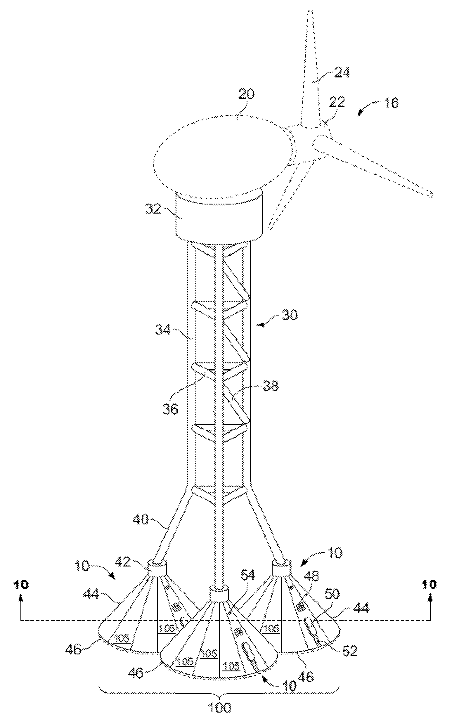
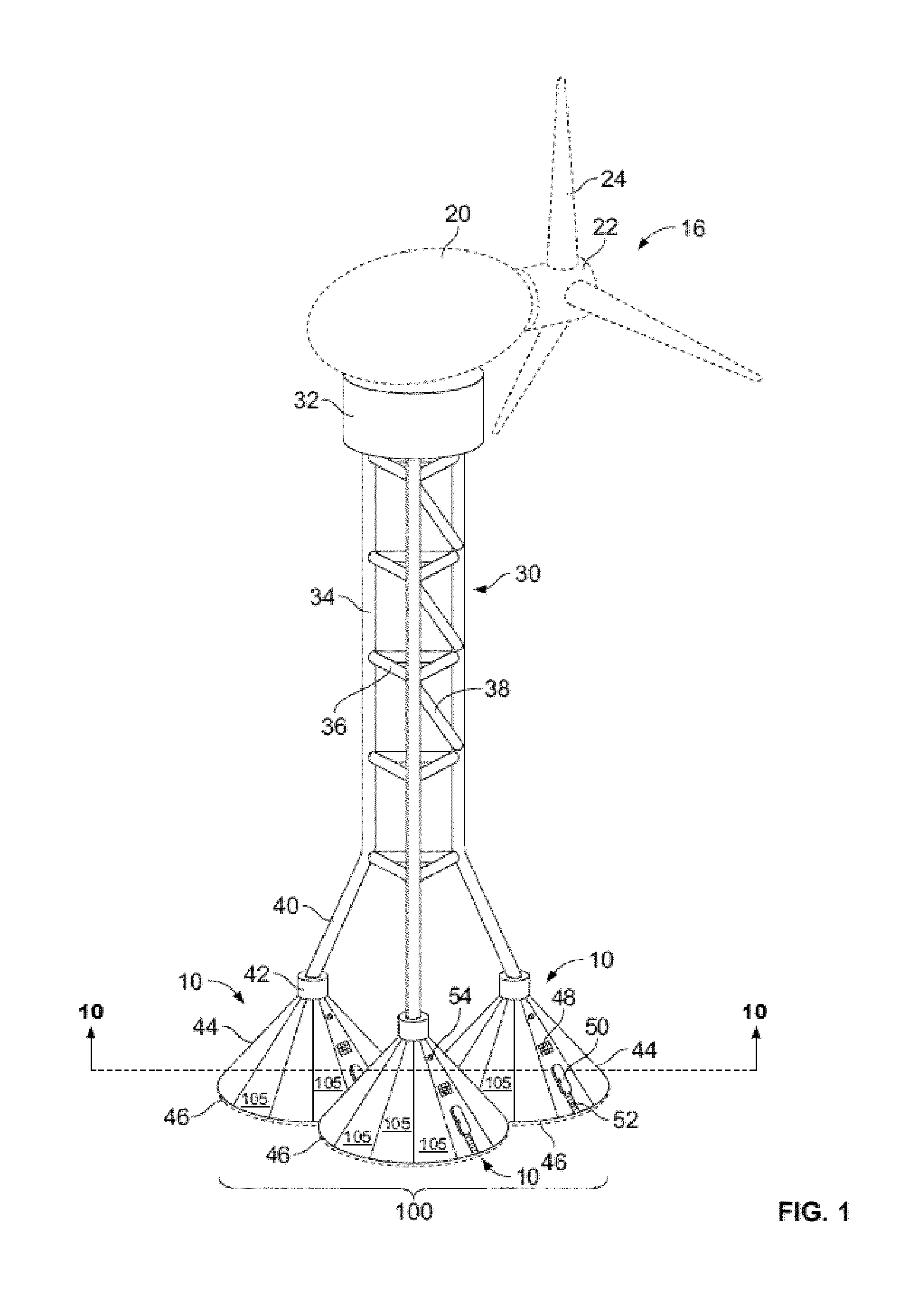
[0024]As shown in FIG. 1, a wind turbine 16 generally includes a nacelle 20 housing a generator (not shown). Nacelle 20 is mounted atop a tower transition piece 32 with a flange (not shown) on top of a space frame tower 30. The height of tower 30 is selected based upon factors and conditions known in the art, and may extend to heights of 60 meters or more. The wind turbine 16 may be installed on any terrain providing access to areas having desirable wind conditions. The terrain may vary greatly and may include, but is not limited to, mountainous terrain or off-shore locations. Wind turbine 16 also comprises a rotor 22 that includes one or more rotor blades 24 attached to a rotating hub. Although wind turbine 16 shown in FIG. 1 includes three rotor blades 24, there are no specific limits on the number of rotor blades 24 required by the present invention. Space frame tower 30 includes a plurality of vertical tower support members 34, a plurality of horizontal tower support members 36,...


PUM


Abstract

A modular surface foundation for wind turbine space frame towers, an apparatus to form panels of housing members of modular surface foundation, and method of forming the modular surface foundation for wind turbine space frame towers is provided. The modular surface foundation comprises a plurality of footing members, and a housing member disposed on each of the footing members, the housing members extending from the footing members and attaching to one or more structural members forming a portion of a wind turbine tower, wherein the housing member provides support and increased height for the space frame tower and includes an interior space.

Description

FIELD[0001]The present disclosure is directed to a modular surface foundation for wind turbine space frame towers, an apparatus to form a plurality of panels of the housing member of the modular surface foundation, and a method of forming the modular surface foundation for wind turbine space frame towers.BACKGROUND[0002]Recently, wind turbines have received increased attention as environmentally safe and relatively inexpensive alternative energy sources. With this growing interest, considerable efforts have been made to develop wind turbines that are reliable, efficient, and cost effective to install.[0003]Generally, a wind turbine includes a rotor having multiple blades. The rotor is mounted via a hub, main shaft and bearing to a housing or nacelle, which is positioned on top of a truss or tubular tower. Utility grade wind turbines (i.e., wind turbines designed to provide electrical power to a utility grid) can have large rotors (e.g., blade lengths of 30 meters or more). In additi...

Claims


Application Information

Patent Timeline
Patent Type & Authority Applications(United States)
IPC IPC(8): E04H5/04E02D27/32E04B1/19
CPCE02D27/38E02D27/42Y02E10/728F03D11/04F05B2240/9121F03D1/001E02B17/0004E02B2017/0091E02D27/425F03D13/10F03D13/20Y02E10/72F03D13/22F03D80/00
Inventor WILLEY, LAWRENCEZHENG, DANIAN
Owner GENERAL ELECTRIC CO
Why Eureka
Try Eureka