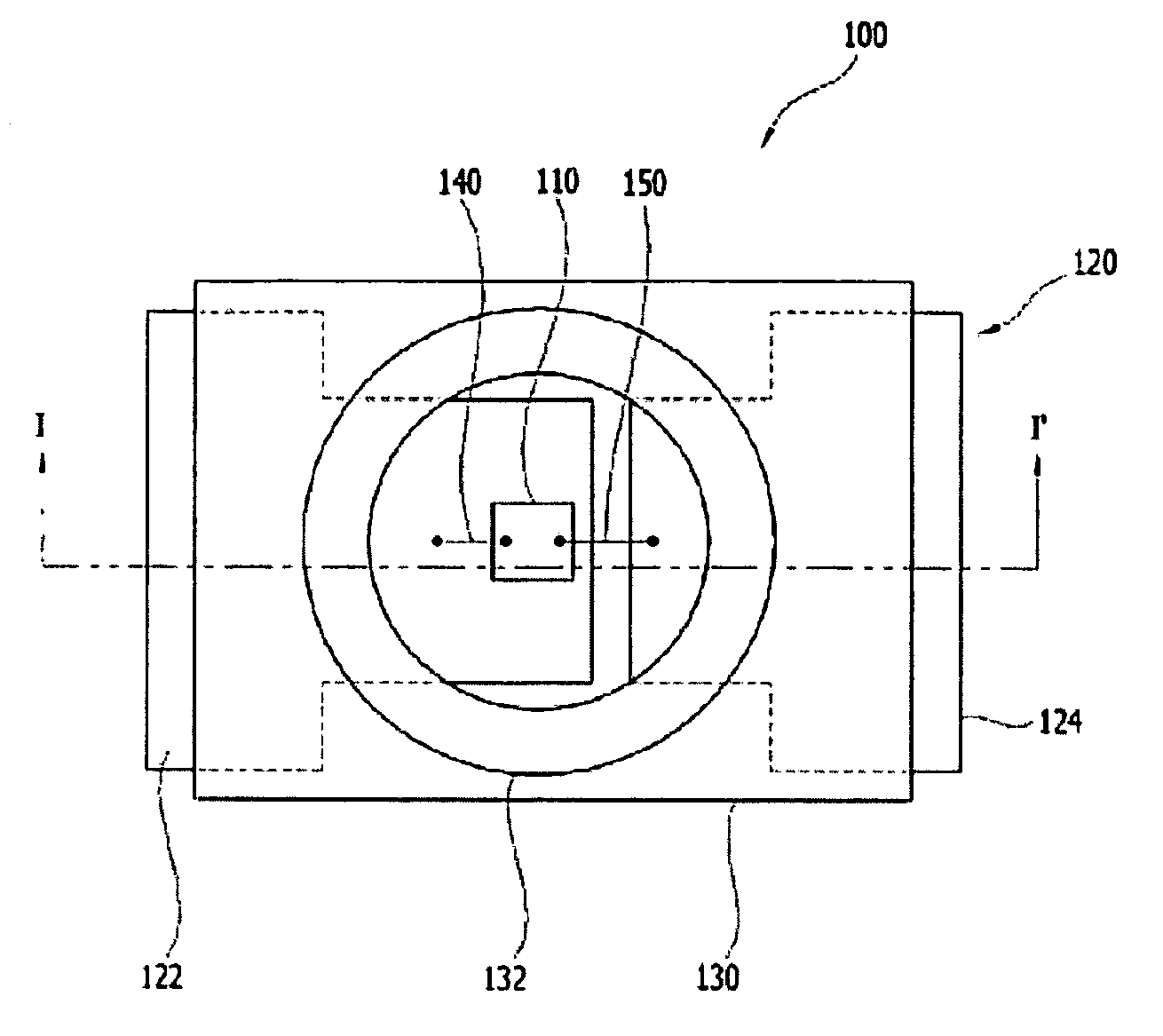
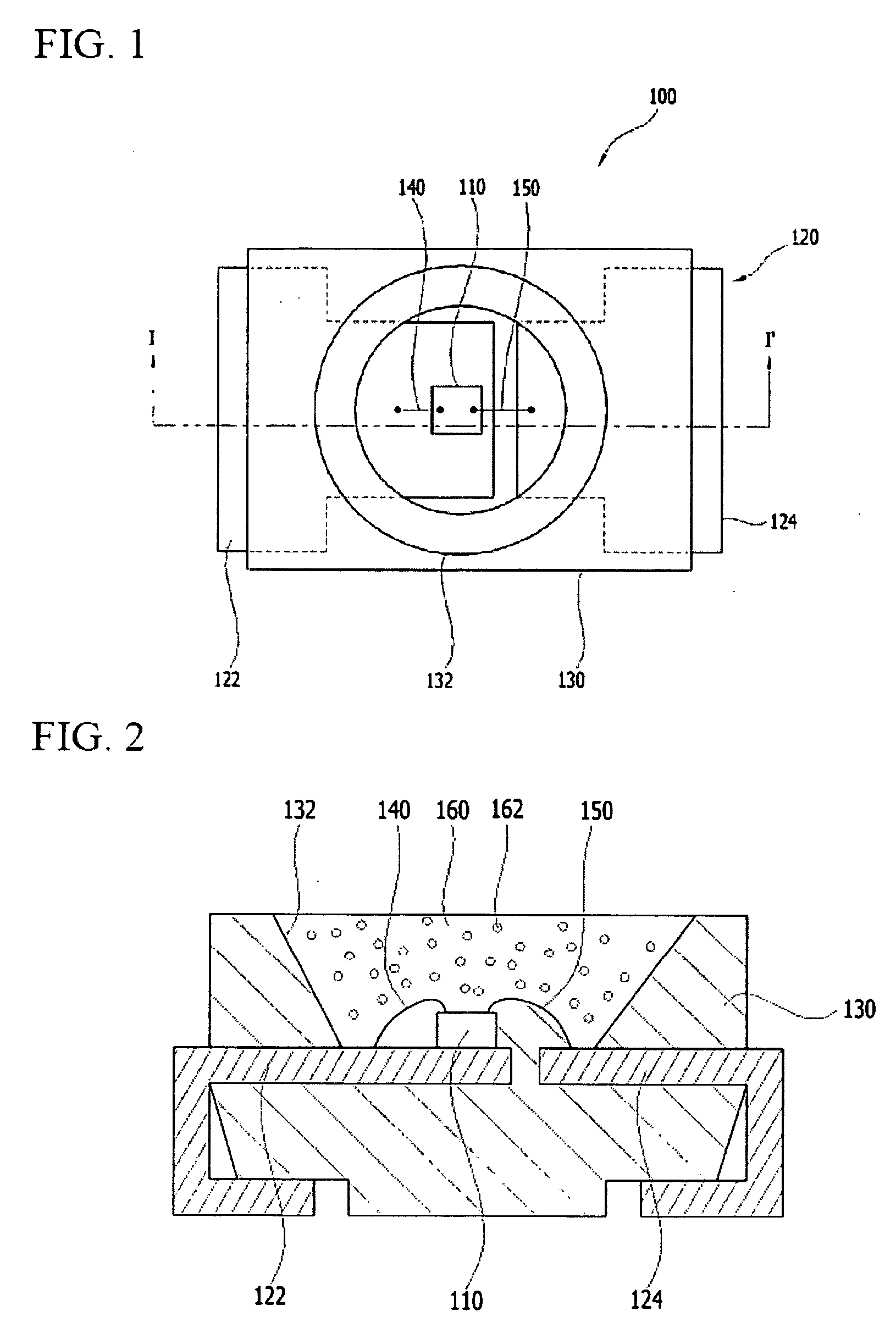
Lead frame, light emitting diode having the lead frame, and backlight unit having the light emitting diode

a technology of light emitting diodes and lead frames, which is applied in the direction of electrical equipment, semiconductor devices, semiconductor/solid-state device details, etc., can solve the problems of frame corrosion and darkening, shorten life span, and lower luminance, so as to minimize corrosion and discoloration and high reflectivity

Inactive Publication Date: 2010-06-03
SEOUL SEMICONDUCTOR
View PDF16 Cites 76 Cited by
  • Summary
  • Abstract
  • Description
  • Claims
  • Application Information

AI Technical Summary

Benefits of technology

[0008]The present invention provides a lead frame having high reflectivity while minimizing corrosion and discoloration.
[0009]The present invention also provides a light emitting diode (LED) having the lead frame to have high reflectivity.

Problems solved by technology

However, the lead frame coated with silver (Ag) may be vulnerable to moisture and heat, so that when the LED is used for a long time, the lead frame is corroded and darkened to lower luminance and shorten life span.
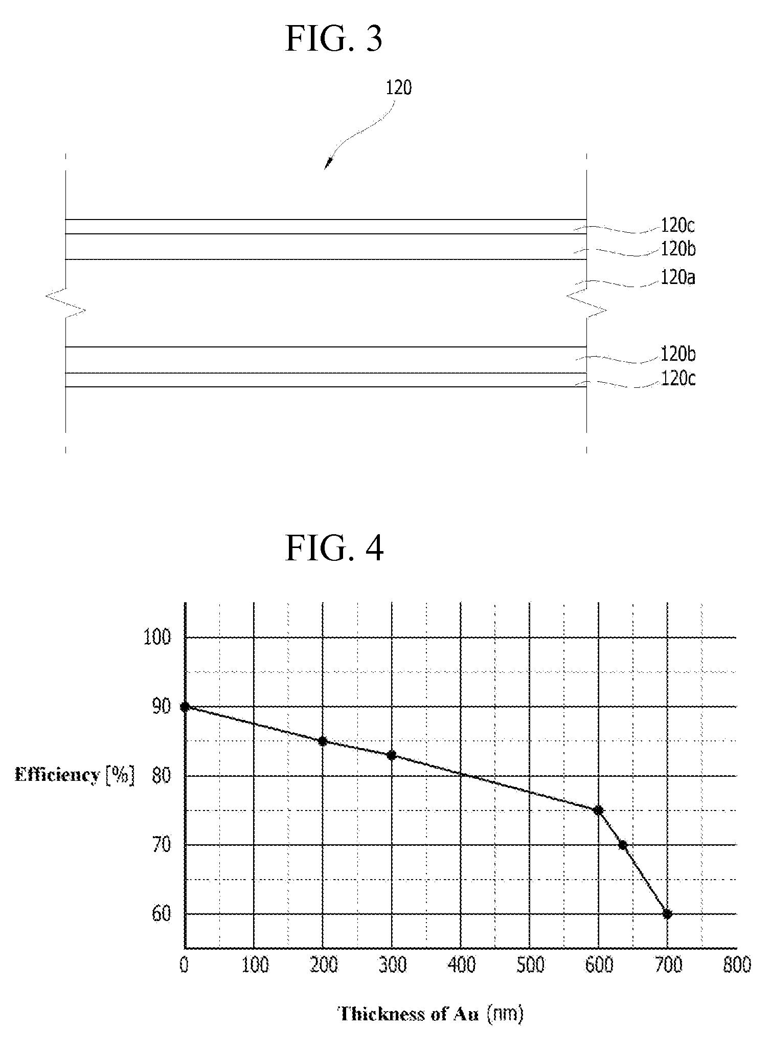
In order to solve the corrosion problem, a lead frame coated with gold (Au) instead of silver was developed, but gold (Au) has relatively low light reflectivity that may lower efficiency of an LED.

Method used


Image

  • Lead frame, light emitting diode having the lead frame, and backlight unit having the light emitting diode
  • Lead frame, light emitting diode having the lead frame, and backlight unit having the light emitting diode
  • Lead frame, light emitting diode having the lead frame, and backlight unit having the light emitting diode

Examples


Embodiment Construction

[0056]The present invention is described more fully hereinafter with reference to the accompanying drawings, in which example embodiments of the present invention are shown. The present invention may, however, be embodied in many different forms and should not be construed as limited to the example embodiments set forth herein. Rather, these example embodiments are provided so that this disclosure will be thorough and complete, and will fully convey the scope of the present invention to those skilled in the art. In the drawings, the sizes and relative sizes of layers and regions may be exaggerated for clarity.

[0057]It will be understood that when an element or layer is referred to as being “on,”“connected to” or “coupled to” another element or layer, it can be directly on, connected or coupled to the other element or layer or intervening elements or layers may be present. In contrast, when an element is referred to as being “directly on,”“directly connected to” or “directly coupled ...


PUM


Abstract

An LED includes a light-emitting chip, a metal member, and a housing. The light-emitting chip generates light. The light-emitting chip is arranged on the metal member. The housing is combined with the metal member to fix the metal member. The housing has an opening portion exposing at least a portion of the light-emitting chip and the metal member. The metal member includes a base metal layer, a light-reflecting layer arranged on the base metal layer, and a protection layer arranged on the light-reflecting layer and including a metal.

Description

CROSS REFERENCE TO RELATED APPLICATION[0001]This application claims priority from and the benefit of Korean Patent Application No. 2008-122152, filed on Dec. 3, 2008, and Korean Patent Application No. 2008-129036, filed on Dec. 18, 2008, which are both hereby incorporated by reference for all purposes as if fully set forth herein.BACKGROUND OF THE INVENTION[0002]1. Field of the Invention[0003]The present invention relates to a lead frame, a light emitting diode having the lead frame, and a backlight unit having the light emitting diode. More particularly, the present invention relates to a lead frame of high optical reflectivity and reliability, a light emitting diode having the lead frame, and a backlight unit having the light emitting diode.[0004]2. Discussion of the Background[0005]In general, a light emitting diode (LED) converts electric energy into light by using compound semiconductor. The LED has merits such as a high efficiency, a long life span, and low power consumption. ...

Claims


Application Information

Patent Timeline
Patent Type & Authority Applications(United States)
IPC IPC(8): H01L33/00H01L23/495
CPCH01L33/46H01L33/62H01L2224/48091H01L33/60H01L2224/48247H01L2924/00014H01L2924/181H01L2924/00012
Inventor CHO, JAE-HOYOON, SEAN-JHINKIM, TAE-KWANGKIM, KYUNG-NAM
Owner SEOUL SEMICONDUCTOR
Why Eureka
Try Eureka