
Eddy Current Testing Method, Steel Pipe or Tube Tested by the Eddy Current Testing Method, and Eddy Current Testing Apparatus for Carrying out the Eddy Current Testing Method

a technology of eddy current testing and testing method, which is applied in the direction of magnetic measurement, measurement device, instruments, etc., can solve the problems of deterioration of corrosion resistance, variation in determination, and fear of breakage, and achieve the effect of high hardness

Active Publication Date: 2010-06-03
NIPPON STEEL CORP
View PDF5 Cites 7 Cited by
  • Summary
  • Abstract
  • Description
  • Claims
  • Application Information

AI Technical Summary

Benefits of technology

[0012]The present invention was devised to solve the above problems of the conventional arts, and it is an object of the present invention to provide an eddy current testing method capable of securely detecting a high hardness part locally occurring in a metal material having magnetism, and capable of securely checking whether the high hardness part has been removed after execution of a repairing treatment for removing the high hardness part, a steel pipe tested by the eddy current testing method, and an eddy current testing apparatus for carrying out the eddy current testing method.
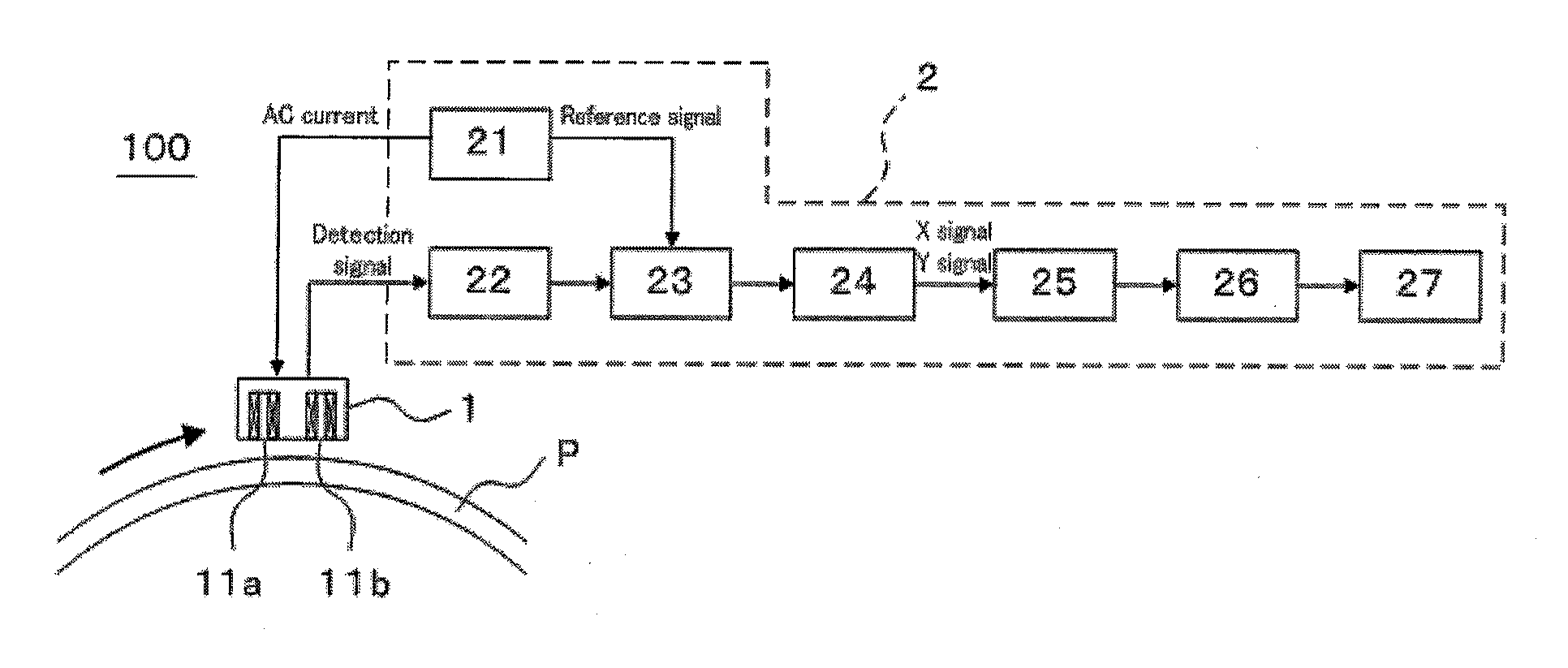
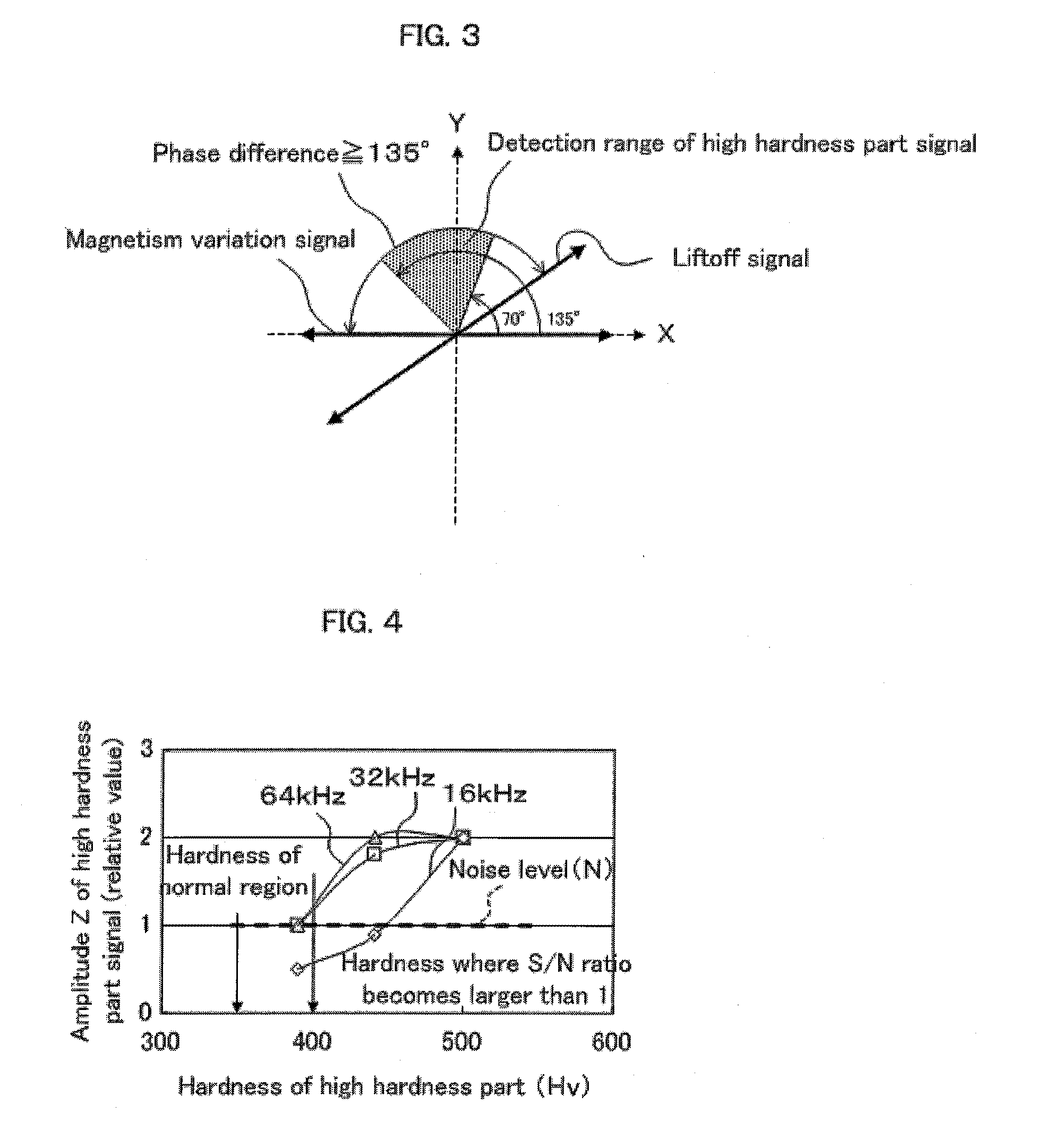
[0014](1) By using a so-called self comparison type differential coil, it is possible to suppress an amplitude of a detection signal resulting from variation in magnetism which is inherent to a metal material (magnetism variation signal), and an amplitude of a detection signal resulting from liftoff variation between the metal material and the differential coil (in particular, detection coil) (liftoff signal).
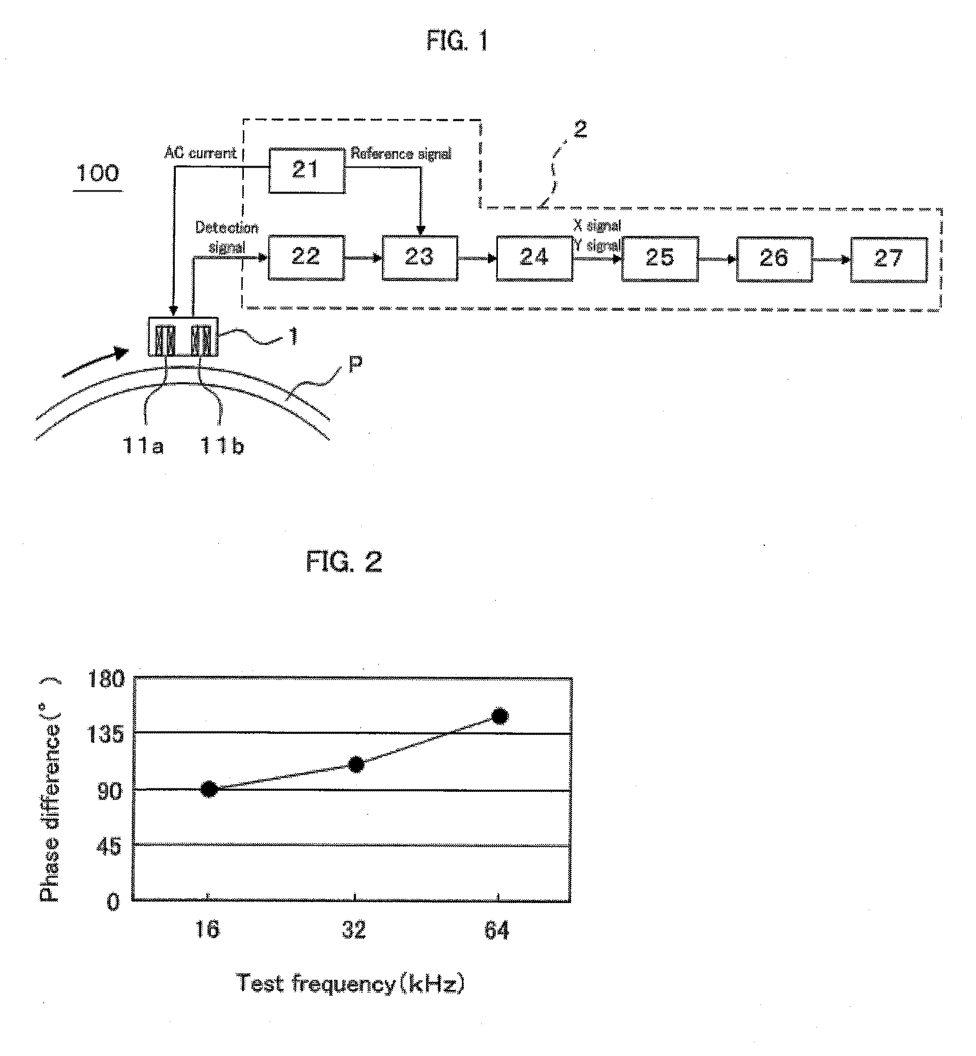
[0015](2) By adjusting a frequency of an AC current for energizing the differential coil (test frequency), it is possible to adjust a phase difference between the magnetism variation signal and the liftoff signal.
[0017](4) Therefore, it is possible to securely detect the high hardness part by using not only the amplitude but also the phase of detection signal outputted from the differential coil after adjustment of test frequency, as information for detecting the local high hardness part locally occurring in the metal material.
[0025]According to the present invention, it is possible to securely detect a high hardness part locally occurring in a metal material having magnetism, and to securely check whether the high hardness part has been removed after execution of a repairing treatment for removing the high hardness part.

Problems solved by technology

When such a local high hardness part occurs in a metal material, there arises a fear of breakage due to embrittlement of the metal material and deterioration in corrosion resistance in the high hardness part.
However, detecting a high hardness part and checking removal of the high hardness part by visual inspection, or by using a simplified hardness meter which measures hardness by magnitude of press fit or ultrasonic resonance frequency of an indenter, after press-fitting the indenter into a metal material inconveniently spend time due to difficulty in continuous measurement, and cause variation in determination.
However, when the metal material is a magnetic material, it is sometimes the case that accurate detection of a high hardness part is difficult because a detection signal resulting from magnetism variation (magnetism unevenness) which is inherent to the metal material, and a detection signal resulting from distance (liftoff) variation between the metal material and a detecting coil are superimposed as noises, with respect to a detection signal in the local high hardness part at the time of carrying out an eddy current testing.
Further, the region where the high hardness part is removed by grinding or the like shows larger noise signal due to liftoff variation because the surface of the metal material is ground.

Method used


Image

  • Eddy Current Testing Method, Steel Pipe or Tube Tested by the Eddy Current Testing Method, and Eddy Current Testing Apparatus for Carrying out the Eddy Current Testing Method
  • Eddy Current Testing Method, Steel Pipe or Tube Tested by the Eddy Current Testing Method, and Eddy Current Testing Apparatus for Carrying out the Eddy Current Testing Method
  • Eddy Current Testing Method, Steel Pipe or Tube Tested by the Eddy Current Testing Method, and Eddy Current Testing Apparatus for Carrying out the Eddy Current Testing Method

Examples


Embodiment Construction

[0030]In the following, one preferred embodiment of the present invention will be explained with reference to attached drawings as appropriate, for the case where a metal material which is a material to be tested is a steel pipe (duplex stainless steel) having magnetism, as an example.

[0031]

[0032]FIG. 1 is a schematic view showing an outline structure of an eddy current testing apparatus according to one embodiment of the present invention. As shown in FIG. 1, the eddy current testing apparatus 100 according to the present embodiment comprises a differential coil 1 and a signal processor 2.

[0033]The differential coil 1 is disposed to be opposite to an outer surface of a steel pipe P for inducing an eddy current by making an AC magnetic field act on the steel pipe P, and detecting the eddy current induced in the steel pipe P. To be more specific, the differential coil 1 according to the present embodiment is a mutual induction type coil in which an excitation coil (not shown) for mak...


PUM


Abstract

It is an object of the present invention to provide an eddy current testing method capable of securely detecting a high hardness part locally occurring in a metal material having magnetism, and capable of securely checking whether the high hardness part has been removed after execution of a repairing treatment for removing the high hardness part.In the eddy current testing method according to the present invention, a frequency of the AC current for energizing the differential coil 1 is set so that a phase difference between a magnetism variation signal of the metal material P and a liftoff signal detected by the differential coil is equal to or larger than 135°, and a local high hardness part occurring in the metal material is detected based on an amplitude and a phase of a detection signal outputted from the differential coil.

Description

BACKGROUND OF THE INVENTION[0001]1. Field of the Invention[0002]The present invention relates to an eddy current testing method of a metal material such as a steel pipe or tube having magnetism, a steel pipe or tube tested by the eddy current testing method, and an eddy current testing apparatus for carrying out the eddy current testing method. In particular, the present invention relates to an eddy current testing method capable of securely detecting a high hardness part locally occurring in a metal material, and capable of securely checking whether the high hardness part has been removed after execution of a repairing treatment such as grinding for removing the high hardness part, a steel pipe or tube tested by the eddy current testing method, and an eddy current testing apparatus for carrying out the eddy current testing method. Hereinafter, “pipe or tube” is referred to as “pipe” when deemed appropriate.[0003]2. Description of the Related Art[0004]In a production process of a me...

Claims


Application Information

Patent Timeline
Patent Type & Authority Applications(United States)
IPC IPC(8): G01R33/12
CPCG01N27/9053
Inventor HYODO, SHIGETOSHIKUREISHI, SATOSHI
Owner NIPPON STEEL CORP
Learn More