Hand-held self-referenced apparatus for three-dimensional scanning

a three-dimensional scanning and self-reference technology, applied in the field of three-dimensional scanning, can solve the problems of not being able to ensure that an accurate estimate of the pose is maintained, noisy enough to limit the quality of integrated data, and using a positioning device significantly increases the complexity and cost of the apparatus

Active Publication Date: 2010-06-03
CREAFORM INC
View PDF10 Cites 92 Cited by
  • Summary
  • Abstract
  • Description
  • Claims
  • Application Information

AI Technical Summary

Benefits of technology

[0011]For large objects, it is a great advantage to capture large sets of positioning markers in one or a few snapshots. Using a high-resolution photogrammetric camera, one can actually obtain higher accuracy on the integrated sets of markers into a single model, after bundle adjustment. These markers are typically stuck on the surface of the object at a distance of 10 to 15 cm between each other. The photogrammetric camera makes it possible to capture an accurate model when viewed at a farther distance such as for example, more than 1.5 m. Using this 3D model of the positioning markers, one can then use a self-referencing laser scanner to gather sets of high density 3D surface points on the surface of an object. The density of these 3D surface points may easily exceed several points per square millimeter. For that purpose, the laser scanner calculates its position and orientation from the observed positioning markers and matches them with the 3D model of these markers. The laser scanner then benefits from an accurate model of the markers while measuring dense sets of points at short distance, typically from 250 to 400 millimeters to the object's surface. Actually, when using triangulation-based 3D sensors, the accuracy of these dense sets of points is inversely proportional to the square of the distance between the sensor and the object's surface.
[0012]The present invention thus makes it possible to improve the accuracy of the hand-held self-referencing device described in US Patent Publication No. 2008 / 0201101 for large objects by eliminating these two conflicting objectives. The 3D model of the positioning markers can be captured at a farther distance from the object using the observations from the photogrammetric camera before exploiting this recovered information to help position the self-referenced 3D scanner at short distance from the surface. Consequently, the accuracy of the final high-density surface model can be increased.
[0013]Additionally, the present invention can reduce acquisition time when only separated surface sections of a large object are scanned within the same global coordinate system.

Problems solved by technology

Using a hand-held system, the main challenge is to continuously estimate the position and orientation (6 degrees of freedom) of the apparatus in a global coordinate system fixed relative to the object.
Using a positioning device significantly increases the complexity and cost of the apparatus.
It is also cumbersome or, in some cases, noisy enough to limit the quality of the integrated data.
This idea of integrating the computation of the position directly into the system while exploiting measurement is interesting but these systems depend completely on the geometry of the object and it is not possible to ensure that an accurate estimate of the pose be maintained.
For example, objects whose geometry varies smoothly or objects with local symmetries including spherical, cylindrical or nearly planar shapes, lead to non constant quality in positioning.
These positioning features can be natural points in the scene but in many cases their density or quality is not sufficient and positioning markers are set in the scene.
Nevertheless, there are constraints related to the usage of such a hand-held system.
For larger objects such as vehicles or architectural structures that exceed the working volume size of one cubed meter, this becomes not optimal when it is necessary to scan the whole object surface or when it is necessary to scan sections of these objects but in a common global coordinate system.
Actually, positioning errors accumulate and affect the accuracy of the recovered 3D surface model.

Method used


Image

  • Hand-held self-referenced apparatus for three-dimensional scanning
  • Hand-held self-referenced apparatus for three-dimensional scanning
  • Hand-held self-referenced apparatus for three-dimensional scanning

Examples


Embodiment Construction

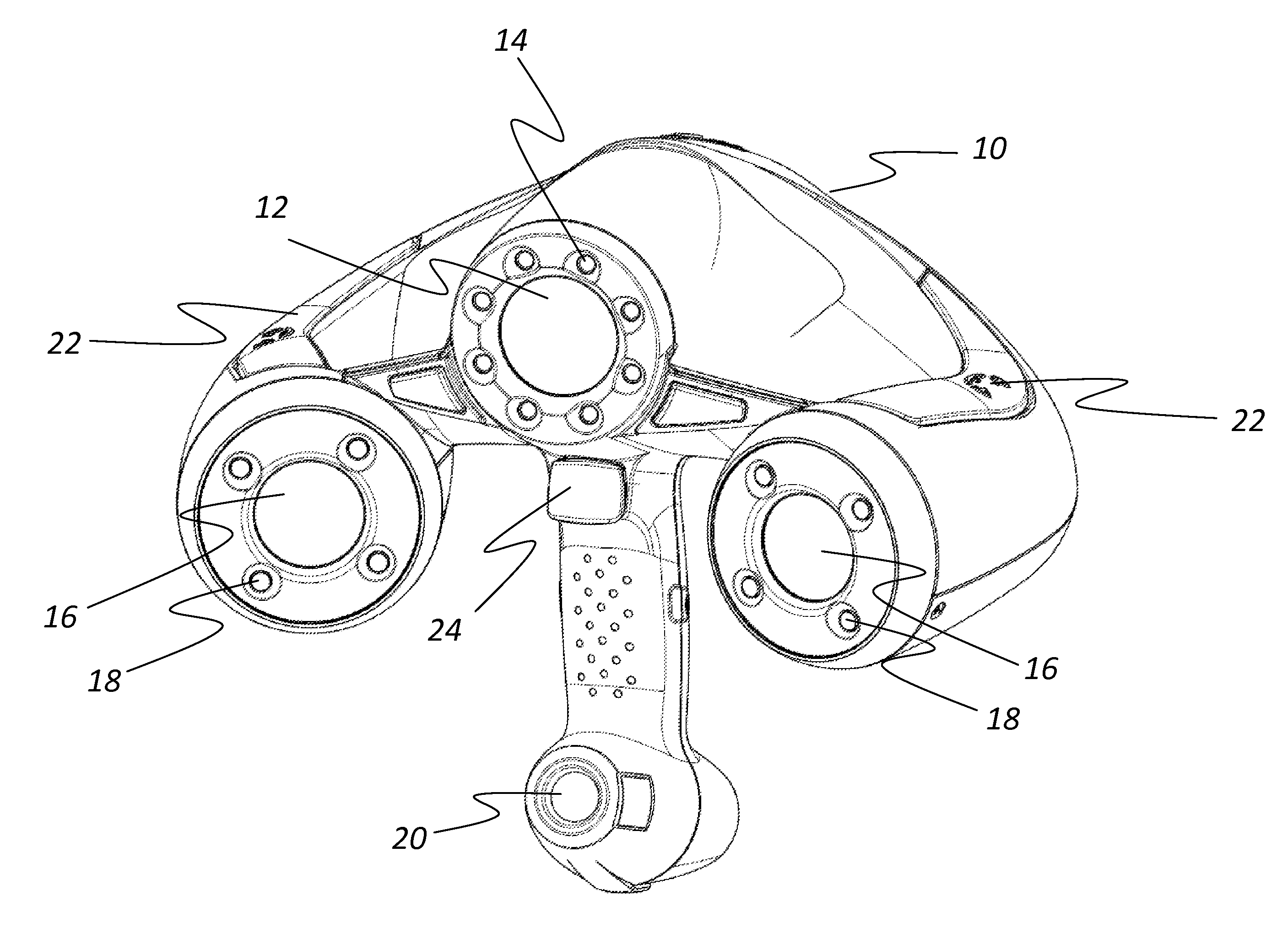
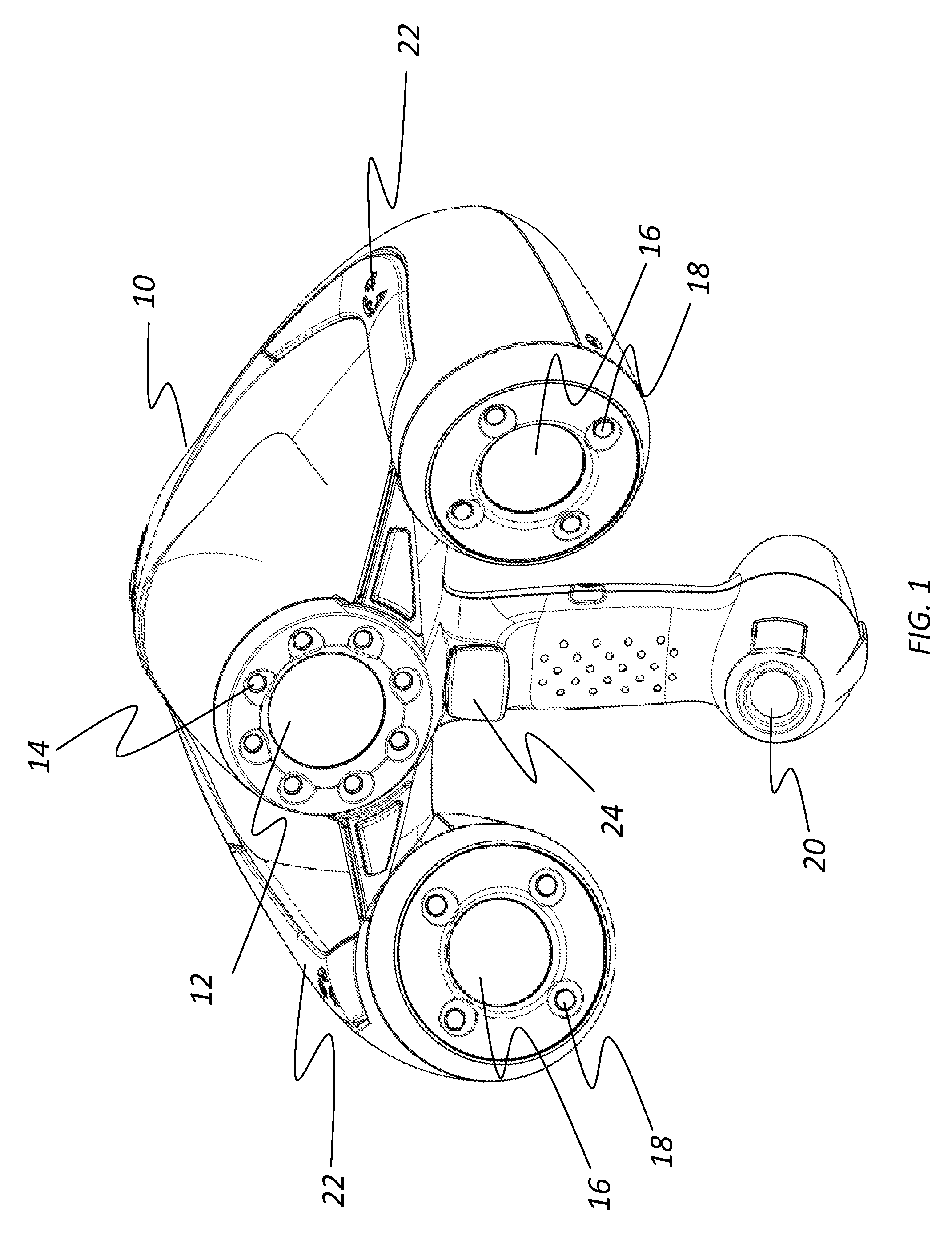
[0027]Referring now to FIG. 1, a 3-D scanning apparatus is generally shown at 10. The 3-D scanning apparatus 10 comprises a set of photogrammetric high-resolution camera with optics and filter 12, hereinafter referred to as photogrammetric camera 12. Different manufacturers of cameras provide cameras with adequate performances (Sony for example). Although there is no restriction on the position of the high-resolution camera, it can, for example, be positioned in the center of the scanning apparatus while aiming forward. The resolution of the high-resolution camera can, for example, exceed two megapixels and the focal length of the optics should be small enough for providing a wide field of view, typically higher than 50 degrees. The optics can be manufactured by Pentax for example. This provides a 1.4 m horizontal field of view at a distance of 1.5 m. The filter is adapted to the light emitting diodes (LEDs) shown at 14. Typically the wavelength is set in the range of red visible sp...


PUM


Abstract

A method and hand-held scanning apparatus for three-dimensional scanning of an object is described. The hand-held self-referenced scanning apparatus has a light source for illuminating retro-reflective markers, the retro-reflective markers being provided at fixed positions on or around the object, a photogrammetric high-resolution camera, a pattern projector for providing a projected pattern on a surface of the object; at least a pair of basic cameras, the basic camera cooperating with light sources, the projected pattern and at least a portion of the retro-reflective markers being apparent on the 2D images, a frame for holding all components in position within the hand-held apparatus, the frame having a handle, the frame allowing support and free movement of the scanning apparatus by a user.

Description

CROSS-REFERENCE TO RELATED APPLICATION[0001]The present application is a continuation-in-part of copending U.S. patent application Ser. No. 11 / 817,300 filed Aug. 28, 2007 by Applicants and published under no. US 2008 / 0201101 which is a national stage entry of PCT patent application no. PCT / CA06 / 00370 filed Mar. 13, 2006 which in turn claimed priority of U.S. provisional patent application No. 60 / 660,471 filed Mar. 11, 2005, the specifications of which are hereby incorporated by reference.TECHNICAL FIELD[0002]The present invention generally relates to the field of three-dimensional scanning of an object's surface geometry and, more particularly, to a portable three-dimensional scanning apparatus for hand-held operations.BACKGROUND OF THE ART[0003]Three-dimensional scanning and digitization of the surface geometry of objects is commonly used in many industries and services and their applications are numerous. A few examples of such applications are: 3D inspection and measurement of sh...

Claims


Application Information

Patent Timeline
Patent Type & Authority Applications(United States)
IPC IPC(8): H04N13/02
CPCG01C11/02G01B11/2513
Inventor ST-PIERRE, ERICGAGNE, PIERRE-LUCCARON, ANTOINE THOMASBEAUPRE, NICOLASTUBIC, DRAGANHEBERT, PATRICK
Owner CREAFORM INC
Why Eureka
Try Eureka