
Synchronous frequency-shift mechanism in fizeau interferometer

a frequency-shift mechanism and interferometer technology, applied in interferometers, measurement devices, instruments, etc., can solve the problems of introducing aberrations into measurement, requiring alteration of cavity surfaces, and difficult integration of fizeau interferometers with parallel or spatial phase-shifting techniques, etc., to achieve short integration time, high contrast, and high laser power

Active Publication Date: 2010-06-03
ONTO INNOVATION INC
View PDF8 Cites 12 Cited by
  • Summary
  • Abstract
  • Description
  • Claims
  • Application Information

AI Technical Summary

Benefits of technology

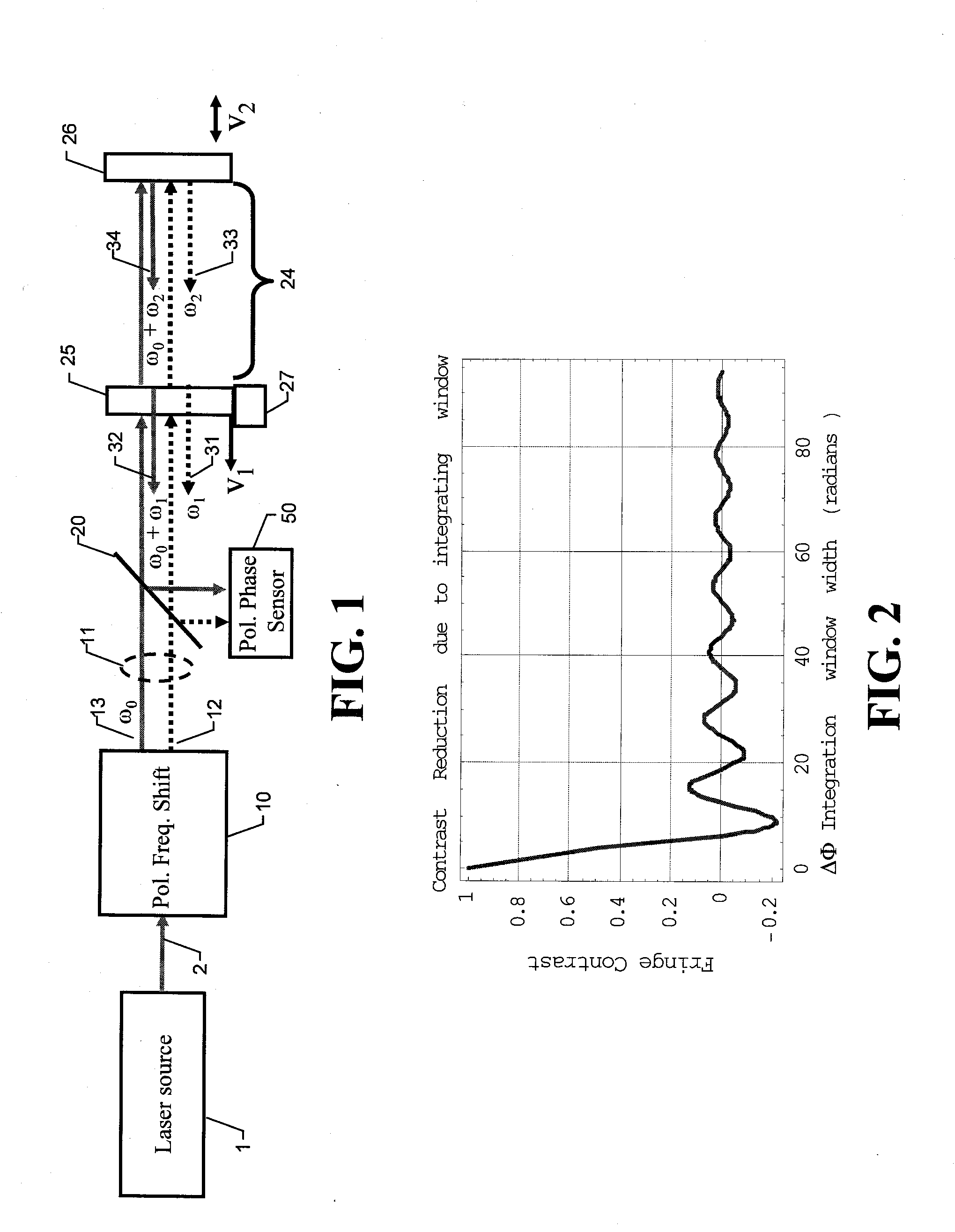
[0016]In another embodiment, a laser source with a periodic coherence function having a repeat length Lc is used. A delay-line is employed in the optical frequency shift device and adjusted to be equal to the Fizeau cavity length minus an integer number of Lc. This ensures that the fringe contrast remains high regardless of the cavity distance. The advantage of utilizing a source with periodic coherence is that higher laser powers, and thus shorter integration times, can be readily achieved.

Problems solved by technology

Integrating a Fizeau interferometer with parallel or spatial phase-shifting techniques has proven somewhat difficult due to the need to encode opposite polarizations from reflections off nominally common optical path components and to a desire not to alter the surfaces or introduce an intra-cavity element.
However, the thin-film coating requires the incident and reflected wavefronts to be at a significant angle with respect to one another and only works over a narrow wavelength band.
In addition, it requires alteration of the cavity surfaces.
Introducing tilt in the Fizeau cavity in order to separate or combine the two polarization components has several undesirable consequences.
First, the separate paths taken by the two polarizations can introduce aberrations into the measurement, particularly when using spherical reference optics.
Thus, the approach of Kuchel et al. requires fine adjustment of the length of the delay path, which is expensive and time consuming to implement.
While the combination of the spatial phase-shift sensor with either the tilted-beam Fizeau or delay-line Fizeau significantly extends the capability of each instrument, it does not overcome the inherent disadvantages of each.

Method used


Image

  • Synchronous frequency-shift mechanism in fizeau interferometer
  • Synchronous frequency-shift mechanism in fizeau interferometer
  • Synchronous frequency-shift mechanism in fizeau interferometer

Examples


Embodiment Construction

[0026]The heart of the invention lies in the recognition that the combination of a polarizing frequency-shifting component with a Fizeau interferometer adapted to produce the same frequency shift can be used advantageously to produce interferograms with orthogonally polarized beams without tilt or the use of short-coherence sources. As used herein, the terms “test surface” and “test object” are mostly used throughout to refer to the surface or object typically placed in a Fizeau interferometer for optical characterization. However, it is understood that a test surface or test object could refer as well to any medium (such as air, water, or glass) being measured for refractive index in-homogeneity in a Fizeau cavity. Therefore, the scope of the invention should be so construed.

[0027]Referring to FIG. 1, a collimated laser source 1 produces a beam 2 that is directed to a polarization frequency-shifting element 10. The polarization frequency-shifting element 10 produces an unshifted be...


PUM


Abstract

An optical device for characterizing a test surface combines a Fizeau interferometer with a polarization frequency-shifting element. Two substantially collinear, orthogonally polarized beams having respective frequencies differing by a predetermined frequency shift are generated by the polarization frequency-shifting element and projected into the Fizeau optical cavity to produce a pair of test beams and a pair of reference beams, wherein the beams in each pair have orthogonal polarization states and have frequencies differing by the predetermined frequency shift. A second, substantially equal frequency shift is introduced in the Fizeau cavity on either one of the pairs of test and reference beams, thereby generating a four-beam collinear output that produces an interferogram without tilt or short-coherence light. The invention may also be implemented by reversing the order of the Fizeau cavity and the polarization frequency-shifting element in the optical train.

Description

RELATED APPLICATIONS[0001]This application is a continuation-in-part application of U.S. Ser. No. 11 / 899,883, filed Sep. 7, 2007, which was based on and claimed the priority of U.S. Provisional Application Ser. No. 60 / 842,754, filed Sep. 7, 2006.BACKGROUND OF THE INVENTION[0002]1. Field of the Invention[0003]The invention relates in general to Fizeau interferometers for optical testing.[0004]2. Description of the Related Art[0005]Phase-shift interferometry is an established method for measuring a variety of physical parameters ranging from the density of gasses to the displacement of solid objects. An interferometric wavefront sensor employing phase-shift interferometry typically consists of a temporally coherent light source that is split into two wavefronts, a reference and a test wavefront, that are later recombined after traveling different path lengths. The relative phase difference between the two wavefronts is manifested as a two-dimensional intensity pattern known as an inte...

Claims


Application Information

Patent Timeline
Patent Type & Authority Applications(United States)
IPC IPC(8): G01B9/02
CPCG01B9/02045G01B9/02057G01B2290/70G01B9/0209G01B9/02065G01B9/02002
Inventor MILLERD, JAMES E.NORTH-MORRIS, MICHAEL
Owner ONTO INNOVATION INC
Learn More