

Bone screw
a bone screw and screw body technology, applied in the field of bone screws, can solve the problems of long screws that cannot always be used, the screw length is too long, and the chips can be irritating adjacent tissues, so as to improve the arrangement of the tool engagement par
Inactive Publication Date: 2010-06-03
WOLTER DIETMAR
View PDF9 Cites 62 Cited by
- Summary
- Abstract
- Description
- Claims
- Application Information
AI Technical Summary
Benefits of technology
[0011]The object of the invention is to make available a bone screw that avoids the aforementioned disadvantages to the greatest possible extent.
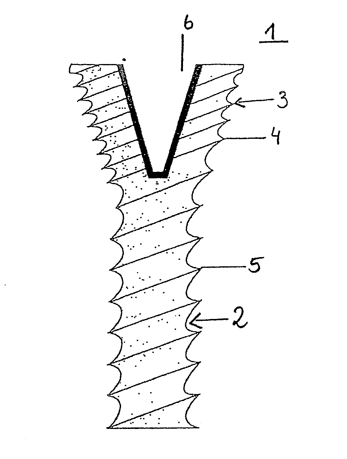
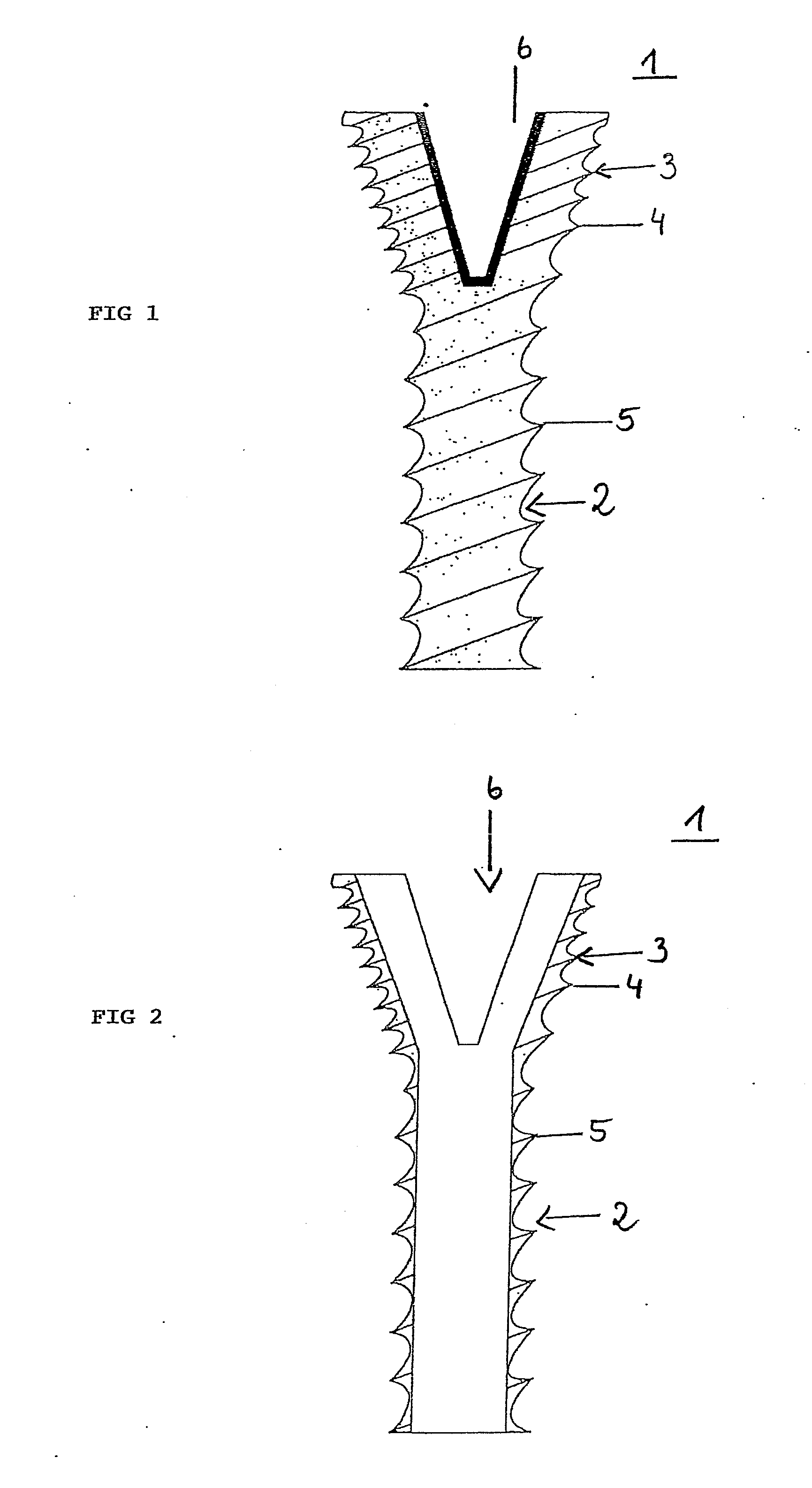
[0013]The invention has recognized that, by continuing the thread in an uninterrupted manner from the shaft into the flared area of the head, a greater contact surface is created between bone screw and bone, resulting in improved distribution and transmission of the loads and forces across the greater load transmission area.
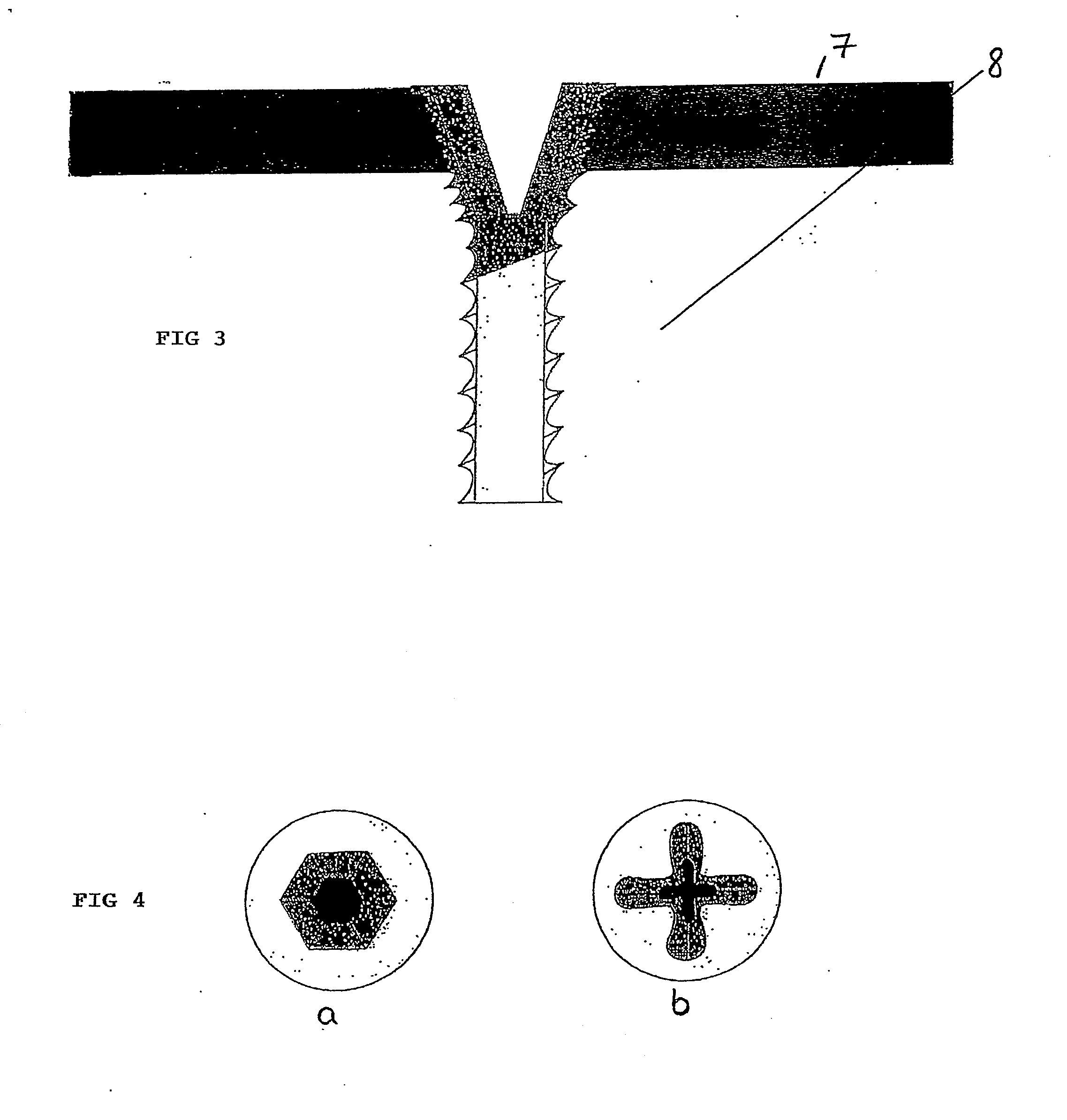
[0014]Surprisingly, it has also been found that engagement of the screw head in the osseous tissue via its flared area directly adjoining the shaft is not a disadvantage as was once assumed (DE 43 43 117). Instead, a larger contact surface between bone screw and bone is additionally created by part of the flared area of the screw head passing through the through-hole in the plate and into the osseous tissue. The loads and forces can thus be transmitted with better distribution.
[0016]In order to ensure an effective blocking of the screw head in the wall of the hole in a bone plate, the head area, in a preferred embodiment of the invention, has a multi-run thread, for example a double-run thread, with the thread pitch being maintained. As the bone screw is screwed into the bone, the lower head area engaging in the bone with its double-run thread can utilize the thread already formed in the bone by the bone thread of the shaft. This is because the bone thread of the screw has cut a thread into the wall of the bone hole, such that a flank of the double-run thread of the head here has direct contact with the bone tissue. The second thread turn of the double-run thread, however, has to cut independently into the bone. To be able to do this efficiently, it is advantageous that the thread edges of the double-run thread are self-tapping. The thread of the head engaging in the bone can expediently have elongate recesses so as to be able, if appropriate, to take up any bone substance that is formed during the cutting process.
[0018]The invention has recognized that within the aforementioned angle ranges, particularly within the preferred angle ranges, the undesired formation of chips mentioned in the introduction can be avoided to a very large extent. This is confirmed by Examples 2 to 5. It is assumed that the elongate head shape of the bone screw leads to more uniform and stronger pressing of the deformed material in the wall of the hole and, in this way, chips that may emerge from the hole can be effectively avoided.
[0019]A further advantage of the head shape predetermined by the preferred angle ranges is the improved arrangement of a tool engagement part on the screw head, for example a torx socket or hexagon socket for receiving a suitable screwdriver tool. Since the screw head narrows only slowly in the direction of the shaft, it is possible to make the recess for the tool, for example for a screwdriver, deeper and, therefore, of smaller diameter, without weakening the wall in the head area. If the head of the bone screw is a cone, then the angle of the cone of the recess expediently corresponds to the angle of the head cone. Here, the wall thickness between the recess and the outer contour of the head remains unchanged. A trumpet-shaped configuration of the recess is also advantageous in which the entry point of the tool engagement part is wider and this width decreases in a trumpet shape toward the interior of the head. This ensures that the force transmission is generated over a larger contact surface and, consequently, that destruction of the recess in the screw head and also in the area of the tool, e.g. the blade of the screw driver, is avoided.
Problems solved by technology
However, long screws cannot always be used since, for example, limits are imposed on the screw length by the anatomy of the bones.
This is also seen as a disadvantage for reasons relating to compatibility, not least because the chips represent a foreign body that can trigger corresponding foreign-body reactions in the surrounding tissue.
Moreover, there is a risk of emerging chips irritating the adjacent tissue.
The fact that pure titanium has soft material properties and that a titanium alloy has harder material properties leads to a deformation of the material in the area of the wall of the hole in the plate if a threaded conical screw head made of a titanium alloy is screwed into the hole made of pure titanium.
In this area, fatigue fractures can occur under excessive loads.
Method used
View moreImage
Smart ImageViewing Examples

Examples
example 1
[0042]Standard plates of titanium 1 measuring 125×20×2.5 (L×B×H) with 12 holes. Screwing of bone screws (type tifix® MINI 1—titanium 4 (high-strength pure titanium)) into synthetic bone, with different conical head geometry (14.5°, 16°, 17.5°) and defined screwing-in angles (5°, 10°). Starting torque=2.5-3 Nm.
example 2
[0043]Bone screws with a 17.5° conical head were tested at a screwing-in angle of 5° according to the test setup described in Example 1. In 3 of 5 cases, chip formation was visible in the blocked state.
example 3
[0044]Bone screws with a 16° conical head were tested at a screwing-in angle of 5° according to the test setup described in Example 1. In 3 of 5 cases, chip formation was visible in the blocked state.
Login to View More PUM
 Abstract
The invention relates to a bone screw with a shaft that defines a longitudinal axis and with a head that is configured as a thickened portion, said shaft and head being threaded. The thread of the shaft (bone thread) merges in an uninterrupted manner into the thread on the flared area of the head adjoining the shaft. As a result, part of the threaded head lies in the osseous tissue, giving a larger contact surface between bone screw and bone and improving the distribution and transmission of the loads and forces.
Description
REFERENCE TO RELATED APPLICATIONS[0001]This application is a national stage application under 35 USC 371 of International Application No. PCT / EP2007 / 010896, filed Dec. 12, 2007, which claims the priority of German Patent Application No. 10 2006 060 933.6, filed Dec. 20, 2006, the contents of which prior applications are incorporated herein by reference.FIELD OF THE INVENTION[0002]The invention relates to a bone screw with a shaft that defines a longitudinal axis and with a head that is configured as a thickened portion, said shaft and head being threaded, and to a fixation system for bones that comprises a connecting support and a bone screw.BACKGROUND OF THE INVENTION[0003]Bone screws are used in fixation systems for bones with a connecting support in order to connect bone fragments to each other.[0004]The connecting support can be a bone plate, in which case the screw head engaging in a hole of the bone plate is usually blocked at a stable angle with respect to the plate. A connec...
Claims
Login to View More Application Information
Patent Timeline
 IPC IPC(8): A61B17/86
CPCA61B17/8057A61B17/863A61B17/8605
InventorWOLTER, DIETMAR
OwnerWOLTER DIETMAR